Implementing I2C with
an EFM8 Microcontroller
Learn how to
design an I2C interface using the Silicon Labs SMBus peripheral.
Help from Dedicated Hardware
If you've read the articles
listed under “Supporting Information,” you are well aware that I2C is a
relatively complex protocol that requires detailed communication procedures and
a specific circuit configuration. Nevertheless, I2C is widespread, and rightly
so, because in return for this complexity it enables flexible, robust,
low-pin-count serial communication among multiple independent integrated
circuits. It is true that designing an I2C interface “from scratch”—i.e., as
low-level hardware or pure firmware—would be a bit burdensome; fortunately,
though, countless microcontrollers from numerous manufacturers incorporate
peripherals that greatly facilitate I2C implementation. In this two-article
series we will discuss in detail how to incorporate I2C communication into
firmware written specifically for an EFM8 microcontroller, though the concepts
and code presented here are applicable to other Silicon Labs devices.
Furthermore, it would not be difficult to adapt this information to any other
microcontroller—after all, I2C is a standardized protocol that does not vary
from one manufacturer to another.
We will implement I2C using
the SMBus peripheral, which supports both
protocols (SMBus is actually an extension of
I2C, as discussed in a previous
article). Microcontrollers
often function as I2C masters, so master functionality will be our focus, but
slave functionality can be incorporated with similar firmware. This screen
capture from Simplicity Studio summarizes the SMBus peripheral
configuration:
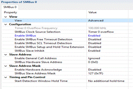
● The source for the serial clock is
chosen as Timer1, and then Timer1 is configured for an overflow frequency of
100 kHz.
● The SMBus is
enabled.
● In this particular system we want to
keep everything as straightforward as possible, so “free timeout detection,”
“SCL timeout detection,” and “setup and hold time extension” are all disabled
(you can read about these features in the EFM8 reference manuals, e.g., this one).
● “Slave inhibit” is enabled because in
this system the EFM8 functions only as a master. You need to disable this
feature if you want the EFM8 to generate an interrupt when another device on
the bus attempts to address the EFM8 as a slave.
● Slave-address properties are not altered
because this example does not incorporate slave functionality. If you want the
EFM8 to function as a slave instead of (or in addition to) a master, you must
set the address that a master device will use to establish communications with
the EFM8. (Refer to the reference manual for an explanation of the “general
call” and “address mask” features.)
● “Hardware acknowledge” is shown as
disabled, though in many cases it is simpler to enable it. When enabled,
the SMBus peripheral will generate an ACK
or NACK without real-time firmware interventionwhen the EFM8 is addressed as a slave or when it
receives a byte during a master/read operation. More information on the
hardware acknowledge functionality is provided toward the end of this article.
● The “start detection window hold time”
feature allows you to modify the timing specifications applied to the detection
of a start bit. This can be used to compensate for major impedance mismatches
between the clock (SCL) and data (SDA) lines. In most cases no such
compensation is necessary.
Now that the peripheral is
configured, we need to enable SMBus0 in the crossbar so that SCL and SDA are
connected to I/O pins. Both pins should be configured for open-drain
input/output, as follows:
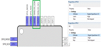
This particular pinout shows
which pins would be assigned to SCL and SDA if you also had the SPI peripheral
enabled.
The Flag
As discussed in a previous article, I2C transactions must follow a specific sequence of events.
It is not surprising, then, that Silicon Labs expects you to implement I2C
communications in the form of a state machine: each event leads the firmware
from one state to another, and the code executed at each stage of the
transaction is determined by the value of the state variable. This is intuitive
enough, but it is important to understand something that might not be
immediately apparent—namely, that the SMBus interrupt
flag is a dominant factor in the operation of the state machine. The interrupt
flag functions like a traffic light, governing the interaction between firmware
traveling east–west and hardware traveling north–south:
● The SMBus hardware
sets the interrupt flag after each event in the transaction.
● When the flag is set, the hardware holds
SCL at logic low, which is essentially the “inactive” clock state because SDA
is allowed to transition when SCL is low. Thus, the bus remains “stalled” as
long as the flag is set.
● I2C-related firmware executes during
this “stalled” condition; this clever arrangement ensures that the processor
has completed its tasks before the bus becomes active again with the next
rising edge of SCL. Even slow processors or lengthy firmware routines are not a
problem with this technique because (as discussed here in
regard to “clock synchronization”) the I2C protocol is designed to support extended
clock-low periods.
● The SMBus interrupt
flag must be cleared by firmware; in fact, the action of setting the flag bit
to zero is what initiates the next hardware event in the I2C transaction. This
is why clearing the flag bit is the final command executed in the code block
assigned to each portion of the state machine.
The Flow
Silicon Labs provides some
very helpful state-machine and event-sequence diagrams in its EFM8 reference
manuals. Let’s start with a master/write operation:
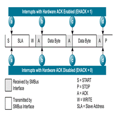
The diagram identifies each
event and its associated interrupt in a typical I2C transaction; the
letters-in-blue-circles correspond to code blocks described in the
corresponding state-machine flowchart (see below). All the data bytes are
transmitted from master to slave, so each ACK is generated by the slave. This
is why the interrupts are the same regardless of whether hardware ACK is
enabled or disabled—the master does not generate any ACKs in a master/write
operation.
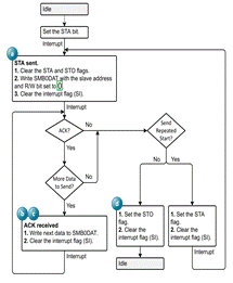
(Note: In some, perhaps all,
of the EFM8 reference manuals, this diagram has a typo indicating that the R/W
bit should be set to 1, instead of 0, for a write operation. The above diagram
has been corrected.) Take a good look at this flowchart, which is highly
informative. Again, notice how each hardware event in the transaction is
followed by an interrupt, and thus each interrupt corresponds to the transition
from one state to another. The key to efficient, clean, reliable I2C code
is a state machine driven by interrupt events: the interrupt service routine is
called when the interrupt flag is set, and then a switch statement is used to
execute a block of code corresponding to the current state of the transaction.
The final statement in each code block resets the interrupt flag bit to zero,
thereby initiating the next hardware event.
Here is the event sequence
for a master/read operation:
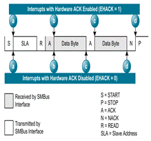
Note the difference in when
the interrupts are generated: If hardware ACK is enabled, the interrupt is
generated after the master (automatically) generates ACK or
NACK based on the preexisting state of the
ACK/NACK bit in the SMBus control register;
the action required by firmware in this case is storing the received byte in
preparation for the next byte. If hardware ACK is disabled, the interrupt is
generated immediately after the last bit of the data byte is received. The “ACK
request” bit in the SMBus control register
is set to indicate that firmware intervention is required, and in response the
firmware should write the appropriate value to the ACK/NACK bit. Then execution
continues with storing the received byte and clearing the interrupt flag.
Here is the master/read
flowchart:
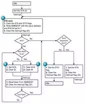
Note the differences here: 1)
R/W is set high instead of low; 2) the master reads from (rather than writes
to) the SMBus data register; and 3) the
master controls the ACK/NACK response in order to confirm that a byte was
successfully received (via ACK) or to indicate that no more data is needed (via
NACK). The EFM8 reference manuals also provide event sequences and a flowchart
for slave functionality.
Conclusion
We have covered the most
important characteristics of the EFM8’s SMBus/I2C
peripheral, and we have also established the foundational concepts for
designing an efficient, robust I2C firmware interface. Part 2 will explore code
development in more detail; sample code for I2C master functio