A Practical Introduction to
Transistors
Basically the function of a
transistor is to amplify a small 'base/emitter' voltage into a much larger
'collector/emitter' voltage. A simple experiment will explain how a transistor
works.
Introduction
Transistors were a revolution,
when they were first developed and introduced way back in 1930 s. They
immediately replaced the cumbersome valves and the triodes in electronic
circuits. Since then till date they are produced and used extensively. These
tiny three-footed parts can be considered as the stepping-stone in the field of
electronics.
In this article we will try to
understand how a transistor works.
What are Transistors
Just like diodes these too are
active semiconductor components, which are available in both silicon and
germanium types.
These can be fundamentally
classified into NPN and PNP categories. We won't discuss its internal
composition or the doping details, since the explanation can be too vast to be
confined in a single article. In simple words a NPN transistor will function
with respect to the ground and accept a positive voltage as a trigger, whereas
a PNP type will work with respect to positive supply and will be triggered with
a negative voltage.
How do they Function
The above functioning can be
explained using a 'lever' analogy. We all know how a small force when applied
to one end of a pivoted lever can be used to displace heavy objects. In an
electronic circuit, transistors behave the same way i.e. a small current when
applied to one of its three terminals ( the base ) a relatively huge current is
allowed to flow through the remaining two leads ( from Collector to Emitter ).
Try it Yourself
The above functioning can be
witnessed practically by doing the following experiment:
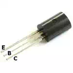
○ Take a general purpose NPN transistor
for eg: BC547B, keeping the printed side towards
you, the right and the left hand side leads are identified as the 'Emitter' and
the 'Collector' respectively, the centre lead is obviously the 'Base'.
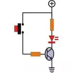
○ Connect ( by soldering
) the cathode ( short lead ) of an LED to the 'Collector', also connect a
resistor of say 150 Ohms to anode ( long lead ) of the LED.
○ Join a resistor of around 10 K to the 'base'
of the transistor.
○ Finally connect a positive supply ( 3 to 12 volts ) to the free end of the 150 Ohms
resistor, and the negative to the 'Emitter' of the transistor.
○ Don't get confused if you find the LED not
glowing, because this is where the actual test begins.
○ As per the Fig. the LED can be switched ON
and Off by applying a small voltage (>0.6 ) to
the free end of the 10 K resistor or the 'Base' of the transistor.
○ For testing purpose you can use the positive
supply itself to toggle the LED. Though this voltage may look quite large,
actually a very small part of it is reaching the 'Base', due to the 10 K
current limiting resistor.
○ This resistor should be dimensioned according
to the 'collector' load ( an LED in this case ),
○ If a PNP transistor is used for the above
experiment, just reverse the polarity of the LED and the supply voltage.
The above experiment must have
provided you a clear picture regarding how does a
transistor work.