Understanding
Analog-to-Digital Converters: Deciphering Resolution and Sampling Rate
Perhaps two of the most
important characteristics to consider during the selection process for analog-to-digital converters (ADCs) are the resolution and
the sampling rate. Before any selection can take place these two factors should
be considered carefully. They will affect everything in the selection process
from price to the underlying architecture of the analog-to-digital
converter required. In order to properly determine the correct resolution and
the correct sampling rate for a specific application, a reasonable
understanding of these characteristics should be obtained.
What follows here are some
mathematical descriptions of the terms associated with analog-to-digital
conversion. The mathematics is important, but the concepts that it represents
are even more important. If you can bear through the mathematics and understand
the concepts introduced, you will be able to narrow down the number of
appropriate ADCs for your application and selection will become that much
easier.
An analog-to-digital
converter converts a continuous signal, either a voltage or a current, into a
sequence of numbers represented by discrete logic levels. The term quantisation
refers to the process of converting a large set of values to a smaller set, or
discrete set, of values. Mathematically, an ADC can be described as quantising
a function with a large domain to produce a function with a smaller domain.
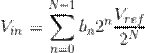
The equation above describes
the analog-to-digital conversion process
mathematically. Here we are describing the input voltage Vin as a series of bits bN-1...b0. In
this formula 2N represents
the number of quantisation levels. It is intuitive that more quantisation
levels result in a more precise digital representation of the original analog signal. For example, if we can represent the
signal with 1024 quantisation levels instead of 256 levels, we have increased
the precision of the ADC because each quantisation level represents a smaller
amplitude range.
Vref represents the maximum input voltage
that can be successfully converted to an accurate digital representation. As
such, it is important that Vref be larger, or the same as, the
maximum value of Vin. Bear in mind, however, that a value
much larger than the value of Vin will result in fewer quantisation
levels representing the original signal. For example, if we know our signal
will never increase above 2.4 V, it would be inefficient to use a voltage
reference of 5 V because over half of the quantisation levels would be unused.
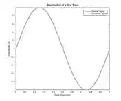
Quantisation Error
Quantisation error is a term
used to describe the difference between the original signal and the discrete
representation of the signal.
![]()
One quantum can be described
as shown above in which A represents the amplitude and the signal spans from A
to -A. N represents the number of bits the signal is quantised to.
Now that we have investigated
quantisation, it is time to see what quantisation means for an ADC. In order to
do this, we need to do some more mathematics. The equation below describes
quantisation error.
![]()
From this, the power in
quantisation error can be defined as shown below.
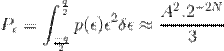
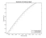
Consider the signal in the
figure above. The power of the signal can be defined as shown in the equation
below.
![]()
Thus, the signal to
quantisation noise ratio (SQNR) can be defined in decibels as shown below. From
this equation it becomes obvious that an ADC with a larger number of
quantisation levels results in an improved SQNR ratio.
![]()
The SQNR value would be the
signal to noise ration (SNR) for an ideal
ADC. Unfortunately, there are other sources of noise associated with the analog-to-digital conversion process. Nevertheless,
determining the SQNR required for your application, by careful analysis and
consideration of the analog signal, will
aid in the selection process. The number of quantisation bits of a given analog to digital converter is know as its resolution.
Characteristic 1: Resolution
- The number of quantisation bits of an ADC.
In most applications, it is
preferable to get the maximum resolution possible. This resolution is often
limited by other considerations such as resources in the digital domain and
cost. As a result, it is important to determine the minimum resolution required
for your application.
Sampling
The continuous time domain
signal not only needs to be quantised in terms of amplitude, it also needs to
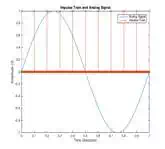
be quantised in terms of time. Consider a train of impulses described as below,
where the term Ts can be defined as the
sampling time period.
![]()
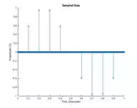
The sampled signal y(t) can be defined mathematically as shown in the equation
below.
![]()
For the impulse train
and analog signal in the figure above, this
results in the impulse train as seen in the figure below.
The Dirac delta function is helpful in describing the concept of sampling
mathematically and will come in useful when looking at signals in the frequency
domain. It is worth mentioning, however, that in real life electronics, these
functions do not exist. Instead, these are replaced with pulses that are close
to rectangular.
The Nyquist Criterion and Shannon’s Theorem
In order to determine the
sampling rate required, it is necessary to take a look at the frequency domain
of the analog signal. This requires again a
few mathematical prerequisites. The Fourier transform of w(t) can be defined as shown in the equation below.
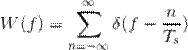
This equation essentially
means that we get a repetition of the Dirac delta function at every harmonic of
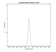
its frequency Fs. Now lets consider an analog signal with the frequency spectrum as shown in
the figure below. The spectrum of the sampled signal Y(f)
it turns out will actually be the convolution of X(f) with W(f).
![]()
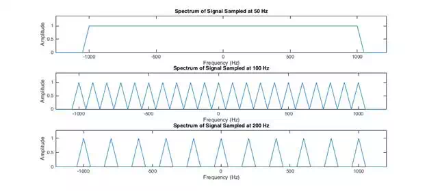
This means that, after
sampling, the signal repeats for all multiples of the sampling frequency. As
shown in the figure below, if the sampling frequency is insufficiently large,
the spectral images of the signal overlap. This minimum frequency is defined as
twice the bandwidth of the signal to be sampled and is know as
the Nyquist Rate.
![]()
As a result of the Nyquist
criterion, it becomes clear that in order to properly specify the correct ADC
for an application, we must know the spectral content of the analog signal.
One way to ensure the Nyquist
criterion is met is to filter the analog signal
prior to digitizing. This is known as an anti-aliasing filter. If we know the
frequency band of interest, we can filter the analog signal
with an anti-aliasing filter to ensure that no frequencies outside of this
range are present before digtizing the
signal with an ADC.
If we look at the figure
above once more, it can easily be seen that after filtering with an appropriate
filter, the spectrum is exactly the same as that of the original signal. No
information is lost and the original signal can be reconstructed. This is known
as Shannon’s Theorem.
Characteristic 2: Sampling
Rate - The frequency at which the analog signal
is sampled.
Both ADC sampling rate and
resolution need to be considered carefully when specifying the ADC required for
an application. Often, a compromise needs to be struck between sampling rate
and resolution in order to accurately and precisely digitize an analog signal. Before specifying an ADC, it is
important to know what sampling rate and what resolution are required. Careful
analysis of the analog signal and the
digital resources required to process the digital data needs to be performed in
order to properly specify the resolution and sampling rate required. This is a
very small part of the complete picture, but provides an introduction to some
of the key concepts associated with analog-to-digital
converters. With a better understanding of quantisation and sampling theorem,
we can ease the selection process to a certain extent by systematically
determining the best ADC for the job.
From here it is necessary to
look at specific ADC architectures in order to determine the best ADC for the
job. This includes:
● Successive Approximation Register ADCs
● Delta-Sigma ADCs
● Flash ADCs