State Diagrams and State Tables
Fundamental to the synthesis of sequential circuits is the concept of internal states. At the start of a design the total number of states required are determined. This is achieved by drawing a state diagram, which shows the internal states and the transitions between them.
All states are stable (steady) and transitions from one state to another are caused by input (or clock) pulses. Each internal state is represented in the state diagram by a circle containing an arbitrary number or letter ; transitions are shown by arrows labelled with the particular input causing the change of state. In the case of pulse outputs the transition arrows are also labeled with the output associated with the input pulse. This will be made clear by examples given below.
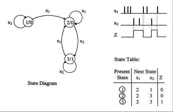
As a simple example, consider a basic counter circuit that is driven by clock pulses (x) and counts in the following decimal sequence: 0,1,2,3,0,1,2,3,0,1,2, etc.
It follows that there are four unique states yielding the following state diagram:
The corresponding state table is derived directly from the above:
It follows that since there are 4 unique states then two flip-flops or secondaries are required in the design. Each flip-flop output can take on the value 0 or 1, giving four possible combinations.
It should be pointed out at the outset that once the state diagram and corresponding state table are derived from the given specification, the design procedure that follows is relatively straightforward.
![]() State Diagrams and State Table Examples
State Diagrams and State Table Examples
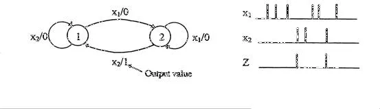
In a circuit having input pulses x1 and x2 the output z is said to be a pulse occurring with the first x2 pulse immediately following an x1 pulse.
State Table: Alternatively:
A pulsed sequential circuit has two input pulses x1, x2 and a single output Z. Z changes to logic ‘1’ with the first x2 pulse immediately following an x1 pulse. Z subsequently goes to ‘0’ when the next x1 pulse occurs
. 
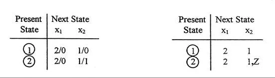
A clocked sequential circuit has two inputs x1, x2. Data on x1 and x2 are synchronized to a clock input to the circuit. Whenever x1x2 = 11 follows x1x2 = 10, the output Z is to become ‘1’. Z remains at ‘1’ until x1x2 = 00, when it returns to ‘0’.

An up/down binary counter comprises a clocked sequential circuit having a level control input x and a clock input. It is required that when x = 0 the counter counts up and when x = 1 the counter counts down.
i.e. x = 0 Count (in decimal notation): 0,1,2,3,0,1,2,3,0,etc
x = 0 Count (in decimal notation): 0,3,2,1,0,3,2,1,0,etc
