MOD Counters
MOD Counters are cascaded counter circuits which count to a set modulus value before resetting
The job of a counter is to count by advancing the contents of the counter by one count with each clock pulse. Counters which advance their sequence of numbers or states when activated by a clock input are said to operate in a “count-up” mode. Likewise, counters which decrease their sequence of numbers or states when activated by a clock input are said to operate in a “count-down” mode. Counters that operate in both the UP and DOWN modes, are called bidirectional counters.
Counters are sequential logic devices that are activated or triggered by an external timing pulse or clock signal. A counter can be constructed to operate as a synchronous circuit or as an asynchronous circuit. With synchronous counters, all the data bits change synchronously with the application of a clock signal. Whereas an asynchronous counter circuit is independent of the input clock so the data bits change state at different times one after the other.
Then counters are sequential logic devices that follow a predetermined sequence of counting states which are triggered by an external clock (CLK) signal. The number of states or counting sequences through which a particular counter advances before returning once again back to its original first state is called the modulus (MOD). In other words, the modulus (or just modulo) is the number of states the counter counts and is the dividing number of the counter.
Modulus Counters, or simply MOD counters, are defined based on the number of states that the counter will sequence through before returning back to its original value. For example, a 2-bit counter that counts from 002 to 112 in binary, that is 0 to 3 in decimal, has a modulus value of 4 ( 00 → 1 → 10 → 11, and return back to 00 ) so would therefore be called a modulo-4, or mod-4, counter. Note also that it has taken four clock pulses to get from 00 to 11.
As in this simple example there are only two bits, ( n = 2 ) then the maximum number of possible output states (maximum modulus) for the counter is: 2n = 22 or 4. However, counters can be designed to count to any number of 2n states in their sequence by cascading together multiple counting stages to produce a single modulus or MOD-N counter.
Therefore, a “Mod-N” counter will require “N” number of flip-flops connected together to count a single data bit while providing 2n different output states, (n is the number of bits). Note that N is always a whole integer value.
The we can see that MOD counters have a modulus value that is an integral power of 2, that is, 2, 4, 8, 16 and so on to produce an n-bit counter depending on the number of flip-flops used, and how they are connected, determining the type and modulus of the counter.
MOD counters are made using “flip-flops” and a single flip-flop can produce a count of 0 or 1, giving a maximum count of 2. There are different types of flip-flop designs we could use, the S-R, the J-K, J-K Master-slave, the D-type or even the T-type flip-flop to construct a counter. But to keep things simple, we will use the D-type flip-flop, (DFF) also known as a Data Latch, because a single data input and external clock signal are used, and is also positive edge triggered.
The D-type flip-flop, such as the TTL 74LS74, can be made from either S-R or J-K based edge-triggered flip-flops depending on whether you want it to change state either on the positive or leading edge (0 to 1 transition) or on the negative or trailing edge (1 to 0 transition) of the clock pulse. Here we will assume a positive, leading-edge triggered flip-flop. You can find more information in the following link about D-type flip-flops.
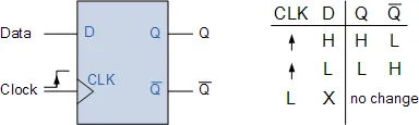
The operation of a D-type flip-flop, (DFF) is very simple as it only has a single data input, called “D”, and an additional clock “CLK” input. This allows a single data bit (0 or 1) to be stored under the control of the clock signal thus making the D-type flip-flop a synchronous device because the data on the inputs is transferred to the flip-flops output only on the triggering edge of the clock pulse.
So from the truth table, if there is a logic “1” (HIGH) on the Data input when a positive clock pulse is applied, the flip-flop SET’s and stores a logic “1” at “Q”, and a complimentary “0” at Q. Likewise, if there is a LOW on the Data input when another positive clock pulse is applied, the flip-flop RESET’s and stores a “0” at “Q”, and a resulting “1” at Q.
Then the output “Q” of the D-type flip-flop responds to the value of the input “D” when the clock (CLK) input is HIGH. When the clock input is LOW, the condition at “Q”, either “1” or “0” is held until the next time the clock signal goes HIGH to logic level “1”. Therefore the output at “Q” only changes state when the clock input changes from a “0” (LOW) value to a “1” (HIGH) making it a positive edge triggered D-type flip-flop. Note that negative edge-triggered flip-flops work in exactly the same way except that the falling edge of the clock pulse is the triggering edge.
So now we know how an edge-triggered D-type flip-flop works, lets look at connecting some together to form a MOD counter.
The edge-triggered D-type flip-flop is a useful and versatile building block to construct a MOD counter or any other type of sequential logic circuit. By connecting the Q output back to the “D” input as shown, and creating a feedback loop, we can convert it into a binary divide-by-two counter using the clock input only as the Q output signal is always the inverse of the Q output signal.
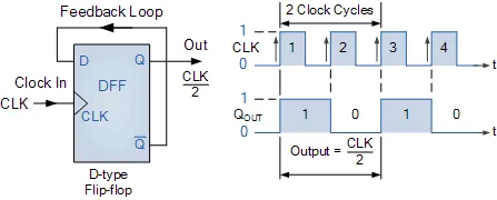
The timing diagrams show that the “Q” output waveform has a frequency exactly one-half that of the clock input, thus the flip-flop acts as a frequency divider. If we added another D-type flip-flop so that the output at “Q” was the input to the second DFF, then the output signal from this second DFF would be one-quarter of the clock input frequency, and so on. So for an “n” number of flip-flops, the output frequency is divided by 2n, in steps of 2.
Note that this method of frequency division is very handy for use in sequential counting circuits. For example, a 60Hz mains frequency signal could be reduced to a 1Hz timing signal by using a divide-by-60 counter. A divide-by-6 counter would divide the 60Hz down to 10Hz which is then feed to a divide-by-10 counter to divide the 10Hz down to a 1Hz timing signal or pulse, etc.