Keyboard Encoder
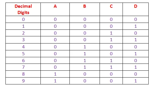
A keyboard encoder is basically decimal to 8-4-2-1 BCD encoder. The truth table for decimal to BCD conversion can be represented like as follows,
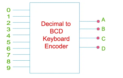
From the above truth table it is cleared that, the logical circuit of this keyboard encoder must have 10 input parts (0 to 9) and four output parts. A, B, C and D.
The circuit can be drawn by using diode and SR flip flops like this
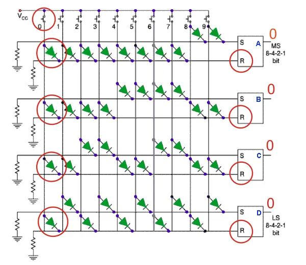
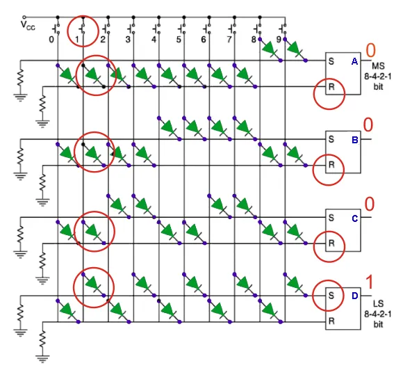
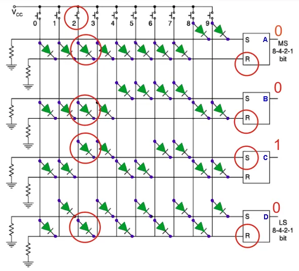
A keyboard encoder is employing a diode matrix. Here, the SR flip flops are used to store the BCD output when once any of the key (0 to 9) is pressed on the actual keyboard. In the circuit the Vcc line of any decimal digit is connected to either S (SET) or R (RESET) input of each flip flop depending upon the BCD equivalent of the said digit. If any key is pressed, flip flops corresponding to the BCD equivalent of the corresponding digit of the key, are SET and RESET depending upon the digit. Suppose 9 is pressed, the Vcc line of 9 is connected to S input of flip flop B and C, through diodes. Hence, flip flop A and D give high output and B and C gives low output. The output of the circuit will become 1001 and from truth table, it is the BCD equivalent of 9. Now suppose key 7 is pressed, then only A is set and B, C and D are reset and the output becomes 1000 which is BCD equivalent of 7. Again when no key is pressed, both R and S are connected to earth with a resistance, hence both S and R will have 0 value so there will be no change flip flop state, hence output of the previously pressed key will remain in the key board encoder unless the next key is pressed.