H Bridge Circuit
An H bridge is an electronic circuit that enables a voltage to be an applied across a load in either direction. The H bridge is a very effective method for driving motors and it finds a lot of applications in many electronic projects especially in robotics.
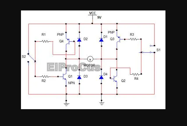
Here four transistors are used which are connected as switches. The two signal lines allow running the motor in different directions. The switch s1 is pressed to run the motor in forward directions and s2 is pressed to run the motor in backward direction. Since the motor needs to dissipate the back EMF, the diodes are used to provide a safer path for the current. The resistors are used to protect the transistors as they limit the base current to the transistors.
In this circuit, when the switch S1 is in ON state, the transistor Q1 is biased to conduction and so is the transistor Q4. The positive terminal of the motor is thus connected to ground potential.
When switch S2 is also ON, the transistor Q2 and transistor Q3 are conducting. The negative terminal of the motor is also connected to ground potential.
Thus with no proper supply, the motor doesn’t rotate. When S1 is OFF, the positive terminal of the motor gets positive voltage supply (as the transistors are cut off). Thus with S1 OFF and S2 ON, the motor is connected in normal mode and starts rotating in forward direction. Similarly when S1 is ON and S2 OFF, the motor gets connected to reverse supply and starts rotating in reverse direction