Digital Circuits and Boolean Logic
Digital or binary logic has fascinated many people over the years. The very idea that a two-valued number system can possibly be the basis for the most powerful and sophisticated computers seems astounding, to say the least. Nevertheless, it is so, and the how and the why of this requires some explanation. Everything in the digital world is based on the binary number system. Numerically, this involves only two symbols: 0 and 1. Logically, we can use these symbols or we can equate them with others according to the needs of the moment. Thus, when dealing with digital logic, we can specify that: 0 = false = no 1 = true = yes Using this two-valued logic system, every statement or condition must be either "true" or "false;" it cannot be partly true and partly false. While this approach may seem limited, it actually works quite nicely, and can be expanded to express very complex relationships and interactions among any number of individual conditions.
Storing Digital/Binary Values
Information can be represented and stored on a variety of electrical/mechanical devices. In many cases, the information relates to measurable variables such as elapsed time or total rainfall or accumulated electrical charge (for which the hourglass, raingauge, and capacitor, respectively, are suitable representation devices). But what about abstract information, such as quantities in mathematics? Here we create an analogy between something that can be stored and measured in an electrical/mechanical device and a mathematical value. For example, we can assign an equivalence between mathematical value and electrical charge. The extent to which we can operate on that electrical charge via the capacitor and our measuring instruments is the degreee to which we can perform analogous mathematical calculations. There are problems, however, with relating mathematics to storable parameters on physical devices. Two of the more important ones are 1) measuring instruments are rarely more accurate than three decimal digits--so mathematics carried out through these devices would have intrinsic limited accuracy; 2) there is typically unrecoverable loss of information--a capacitor could leak away part of its charge, i.e., its analogous mathematical value would arbitrarily change. But there is a solution to these problems: store mathematical values in discrete rather than analog form. Here one uses devices whose variations are limited to discrete states
typically two, e.g., on or off, positive or negative, closed or open. Then, by representing mathematical quantities in a number system having only two digits--a binary number system--any value can be represented with arbitrary accuracy by linking together a sequence of two-state devices and setting the appropriate state for each device. Information integrity in this discrete representation is better than that of analog representation because here information loss requires an arbitrary change of state of a device, not a drift in value. That is much less likely, and there are ways to correct for it.
Logic Gates: AND, OR, NOT, NAND, NOR
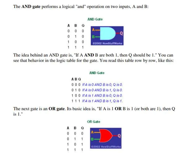
There are five simple gates that you need to learn about. With these simple gates you can build combinations that will implement any digital component you can imagine. The simplest possible gate is called an "inverter," or a NOT gate. It takes one bit as input and produces as output its opposite. The table below shows a logic table for the NOT gate and the normal symbol for it in circuit diagrams:
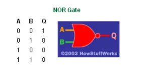
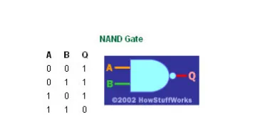
Those are the three basic. It is quite common to recognize two others as well: the NAND and the NOR gate. These two gates are simply combinations of an AND or an OR gate with a NOT gate. If you include these two gates, then the count rises to five. Here's the basic operation of NAND and NOR gates -- you can see they are simply inversions of AND and OR gates: