Digital Circuits - Counters
In previous two chapters, we discussed various shift registers & counters using D flipflops. Now, let us discuss various counters using T flip-flops. We know that T flip-flop toggles the output either for every positive edge of clock signal or for negative edge of clock signal.
An ‘N’ bit binary counter consists of ‘N’ T flip-flops. If the counter counts from 0 to 2푁 − 1, then it is called as binary up counter. Similarly, if the counter counts down from 2푁 − 1 to 0, then it is called as binary down counter.
There are two types of counters based on the flip-flops that are connected in synchronous or not.
Asynchronous Counters
If the flip-flops do not receive the same clock signal, then that counter is called as Asynchronous counter. The output of system clock is applied as clock signal only to first flip-flop. The remaining flip-flops receive the clock signal from output of its previous stage flip-flop. Hence, the outputs of all flip-flops do not change (affect) at the same time.
Now, let us discuss the following two counters one by one.
Asynchronous Binary Up Counter
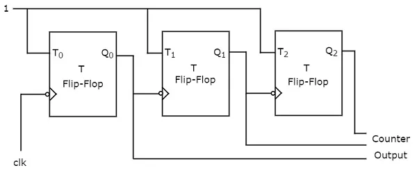
An ‘N’ bit Asynchronous binary up counter consists of ‘N’ T flip-flops. It counts from 0 to 2푁 − 1. The block diagram of 3-bit Asynchronous binary up counter is shown in the following figure.
The 3-bit Asynchronous binary up counter contains three T flip-flops and the T-input of all the flip-flops are connected to ‘1’. All these flip-flops are negative edge triggered but the outputs change asynchronously. The clock signal is directly applied to the first T flip-flop. So, the output of first T flip-flop toggles for every negative edge of clock signal.
The output of first T flip-flop is applied as clock signal for second T flip-flop. So, the output of second T flip-flop toggles for every negative edge of output of first T flip-flop. Similarly, the output of third T flip-flop toggles for every negative edge of output of second T flip-flop, since the output of second T flip-flop acts as the clock signal for third T flip-flop.
Assume the initial status of T flip-flops from rightmost to leftmost is Q2Q1Q0=000Q2Q1Q0=000. Here, Q2Q2 & Q0Q0 are MSB & LSB respectively. We can understand the working of 3-bit asynchronous binary counter from the following table.
No of negative edge of Clock | Q0(LSB) | Q1 | Q2(MSB) |
0 | 0 | 0 | 0 |
1 | 1 | 0 | 0 |
2 | 0 | 1 | 0 |
3 | 1 | 1 | 0 |
4 | 0 | 0 | 1 |
5 | 1 | 0 | 1 |
6 | 0 | 1 | 1 |
7 | 1 | 1 | 1 |
Here Q0Q0 toggled for every negative edge of clock signal. Q1Q1 toggled for every Q0Q0 that goes from 1 to 0, otherwise remained in the previous state. Similarly, Q2Q2 toggled for every Q1Q1 that goes from 1 to 0, otherwise remained in the previous state.
The initial status of the T flip-flops in the absence of clock signal is Q2Q1Q0=000Q2Q1Q0=000. This is incremented by one for every negative edge of clock signal and reached to maximum value at 7th negative edge of clock signal. This pattern repeats when further negative edges of clock signal are applied.
Asynchronous Binary Down Counter
An ‘N’ bit Asynchronous binary down counter consists of ‘N’ T flip-flops. It counts from 2푁 − 1 to 0. The block diagram of 3-bit Asynchronous binary down counter is shown in the following figure.
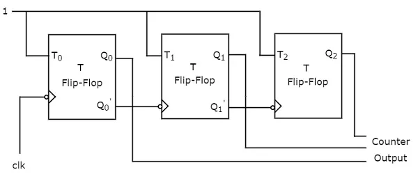
The block diagram of 3-bit Asynchronous binary down counter is similar to the block diagram of 3-bit Asynchronous binary up counter. But, the only difference is that instead of connecting the normal outputs of one stage flip-flop as clock signal for next stage flip-flop, connect the complemented outputs of one stage flip-flop as clock signal for next stage flip-flop. Complemented output goes from 1 to 0 is same as the normal output goes from 0 to 1.
Assume the initial status of T flip-flops from rightmost to leftmost is Q2Q1Q0=000Q2Q1Q0=000. Here, Q2Q2 & Q0Q0 are MSB & LSB respectively. We can understand the working of 3-bit asynchronous binary down counter from the following table.
No of negative edge of Clock | Q0(LSB) | Q1 | Q2(MSB) |
0 | 0 | 0 | 0 |
1 | 1 | 1 | 1 |
2 | 0 | 1 | 1 |
3 | 1 | 0 | 1 |
4 | 0 | 0 | 1 |
5 | 1 | 1 | 0 |
6 | 0 | 1 | 0 |
7 | 1 | 0 | 0 |
Here Q0Q0 toggled for every negative edge of clock signal. Q1Q1 toggled for every Q0Q0 that goes from 0 to 1, otherwise remained in the previous state. Similarly, Q2Q2 toggled for every Q1Q1 that goes from 0 to 1, otherwise remained in the previous state.
The initial status of the T flip-flops in the absence of clock signal is Q2Q1Q0=000Q2Q1Q0=000. This is decremented by one for every negative edge of clock signal and reaches to the same value at 8th negative edge of clock signal. This pattern repeats when further negative edges of clock signal are applied.
Synchronous Counters
If all the flip-flops receive the same clock signal, then that counter is called as Synchronous counter. Hence, the outputs of all flip-flops change (affect) at the same time.
Now, let us discuss the following two counters one by one.
Synchronous Binary Up Counter
An ‘N’ bit Synchronous binary up counter consists of ‘N’ T flip-flops. It counts from 0 to 2푁 − 1. The block diagram of 3-bit Synchronous binary up counter is shown in the following figure.
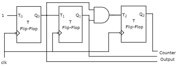
The 3-bit Synchronous binary up counter contains three T flip-flops & one 2-input AND gate. All these flip-flops are negative edge triggered and the outputs of flip-flops change (affect) synchronously. The T inputs of first, second and third flip-flops are 1, Q0Q0 & Q1Q0Q1Q0 respectively.
The output of first T flip-flop toggles for every negative edge of clock signal. The output of second T flip-flop toggles for every negative edge of clock signal if Q0Q0 is 1. The output of third T flip-flop toggles for every negative edge of clock signal if both Q0Q0 & Q1Q1 are 1.
Synchronous Binary Down Counter
An ‘N’ bit Synchronous binary down counter consists of ‘N’ T flip-flops. It counts from 2푁 − 1 to 0. The block diagram of 3-bit Synchronous binary down counter is shown in the following figure.
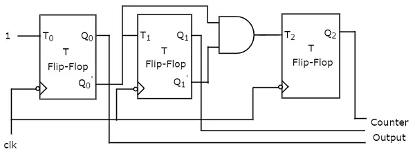
The 3-bit Synchronous binary down counter contains three T flip-flops & one 2-input AND gate. All these flip-flops are negative edge triggered and the outputs of flip-flops change (affect) synchronously. The T inputs of first, second and third flip-flops are 1, Q0′Q0′ &' Q1′Q1′Q0′Q0′ respectively.
The output of first T flip-flop toggles for every negative edge of clock signal. The output of second T flip-flop toggles for every negative edge of clock signal if Q0′Q0′ is 1. The output of third T flip-flop toggles for every negative edge of clock signal if both Q1′Q1′ & Q0′Q0′ are 1.