
A digital circuit is a circuit where the signal must be one of two discrete levels. Each level is interpreted as one of two different states (for example, on/off, 0/1, true/false). Digital circuits use transistors to create logic gates in order to perform Boolean logic. This logic is the foundation of digital electronics and computer processing.
Digital circuits are less susceptible to noise or degradation in quality than analog circuits. It is also easier to perform error detection and correction with digital signals. To automate the process of designing digital circuits, engineers use electronic design automation (EDA) tools, a type of software that optimizes the logic in a digital circuit.
Most of the fundamental electronic components – resistors, capacitors, inductors, diodes, transistors, and operational amplifiers – are all inherently analog. Circuits built with a combination of solely these components are usually analog.

Analog circuits are usually complex combinations of op amps, resistors, caps, and other foundational electronic components. This is an example of a class B analog audio amplifier.
Analog circuits can be very elegant designs with many components, or they can be very simple, like two resistors combining to make a voltage divider. In general, though, analog circuits are much more difficult to design than those which accomplish the same task digitally. It takes a special kind of analog circuit wizard to design an analog radio receiver, or an analog battery charger; digital components exist to make those designs much simpler.
Analog circuits are usually much more susceptible to noise (small, undesired variations in voltage). Small changes in the voltage level of an analog signal may produce significant errors when being processed.
Digital circuits operate using digital, discrete signals. These circuits are usually made of a combination of transistors and logic gates and, at higher levels, microcontrollers or other computing chips. Most processors, whether they’re big beefy processors in your computer, or tiny little microcontrollers, operate in the digital realm.

Digital circuits make use of components like logic gates, or more complicated digital ICs (usually represented by rectangles with labeled pins extending from them).
Digital circuits usually use a binary scheme for digital signaling. These systems assign two different voltages as two different logic levels – a high voltage (usually 5V, 3.3V, or 1.8V) represents one value and a low voltage (usually 0V) represents the other.
Although digital circuits are generally easier to design, they do tend to be a bit more expensive than an equally tasked analog circuit.
It’s not rare to see a mixture of analog and digital components in a circuit. Although microcontrollers are usually digital beasts, they often have internal circuitry which enables them to interface with analog circuitry (analog-to-digital converters, pulse-width modulation, and digital-to-analog converters. An analog-to-digital converter (ADC) allows a microcontroller to connect to an analog sensor (like photocells or temperature sensors), to read in an analog voltage. The less common digital-to-analog converter allows a microcontroller to produce analog voltages, which is handy when it needs to make sound.
An analog circuit works with analog signals—where values change continuously. A digital circuit works with digital signals, where all values are discrete.
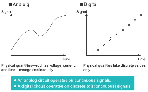
Figure 1 : Analog vs. Digital