OR Gate
An OR gate is the physical realization of logical addition (OR) operation. It is an electronic circuit that generates an output signal of 1, if any of the input signals is also 1.
Two or more switches connected in parallel behave as an OR gate. Observe from the below Figure that the input current will reach the output point when any one of the two switches (A or B) are in ON (1) state. There will be no output only when both the switches are in OFF (0) state
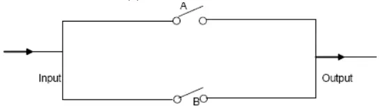
Fig. 5.3 thatdemonstrates Two or more switches connected in parallel behave as an OR gate
Below fig 5.4 shows the truth table and block diagram symbol for an OR gate for two input signals. Notice that the output is 1, when any of the input signals is n 1. It is 0 only when both inputs are 0.

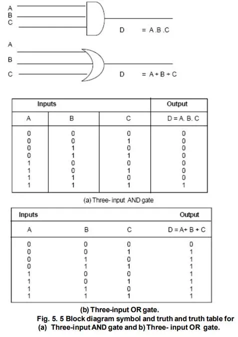
Just as + and. Operations could be extended to several variables by using associative law, AND gates and OR gates can also have more than two inputs. Above shows three-input AND a nd OR gates and the table of all input combinations for each. Notice that the output of the AND gate with inputs A,B and C is 1 only if all three inputs are 1, so that we write the output as A. B. C. Similarly, the OR gate with inputs, A,B, and C has a 1 output if any one of the inputs is 1, so that we write the output as A + B + C.
The above argument can be extended. A four-input AND gate has a 1 output only when all four inputs are 1 and a four-input OR gate has a 1 output when any of its inputs is a 1.