Design of Flexible Pavement
There are various methods of flexible pavement design such as empirical and semi-empirical methods. Flexible pavement design by semi-empirical method is discussed in this article. When a flexible pavement is subjected loading, the stress is maximum at the top layer of pavement. This stress transmits to another layer by point to point contact. Design of flexible pavement is done to bear the all stresses subjected on the top layer.

Flexible Pavement Design by Semi Empirical Method
Following are the semi empirical methods for flexible pavement design:
· Triaxial test method
· Burmister’s method
Triaxial Test Method of Flexible Pavement Design
In this method triaxial test is conducted on soil specimen under 160kN/m2 of lateral pressure. Hence modulus of elasticity is calculated from stress strain curve. Traffic coefficient X and saturation coefficient Y are introduced in this method. These are multiplied with the load system to get the total pavement thickness.
Total pavement thickness by triaxial test method
Where P = wheel load
![]() = design
deflection = 0.25cm
= design
deflection = 0.25cm
E = elasticity modulus
X = traffic coefficient
Y = saturation coefficient
The recommended values of X and Y values with respect to Average Daily Traffic (ADT) and average annual rainfall are tabulated below.
|
ADT (number) |
Traffic coefficient X |
|
40-400 |
½ |
|
401-800 |
2/3 |
|
801-1200 |
5/6 |
|
1201-1800 |
1 |
|
1801-2700 |
7/6 |
|
2701-4000 |
8/6 |
|
4001-6000 |
9/6 |
|
6001-9000 |
10/6 |
|
9001-13500 |
11/6 |
|
13501-20000 |
12/6 |
|
Average annual rainfall (cm) |
Saturation coefficient (Y) |
|
38-50 |
0.5 |
|
51-64 |
0.6 |
|
65-76 |
0.7 |
|
77-90 |
0.8 |
|
91-100 |
0.9 |
|
101-127 |
1.0 |
Burmister’s Method of Flexible Pavement Design:
Burmister introduced a semi empirical method for the design of flexible pavements. In this method, he considered pavement as number of layers. And some assumptions are considered which are as follows:
· The material in each layer is homogeneous
· The material is isotropic
· The material is elastic in nature
· Contact between the layers is continuous
· Unloaded top layer is free from normal and shearing stresses
· The surface layer is infinite in length (horizontal direction) and finite in depth (vertical direction).
· The underlying layers are infinite in both directions.
Burmister given the deformation equations for both flexible and rigid pavements by considering the poisons ratio of soil and pavement material to 0.5.
For flexible pavements
![]()
For rigid pavements
![]()
Where, p = uniform pressure
a = radius of plates
F2 = deflection factor
Es = modulus of the subgrade soil.
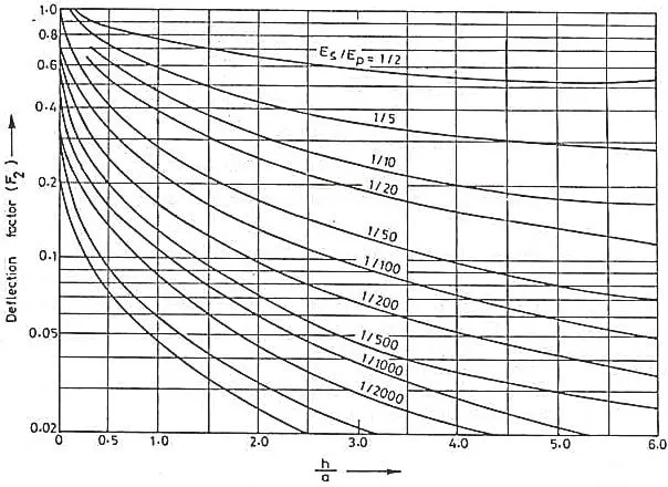
Deflection factor is dependent of ratio of modulus of subgrade soil to the modulus of pavement material. So, from the below graph we can select the value of deflection factor corresponding to the ratio of base layer thickness to the radius of load that is h/a.
Procedure of Flexible Pavement Design by Burmister’s Method
In the Burmister’s design process, firstly conduct plate bearing test on the soil. The diameter of plate used is 30cm. now determine the modulus of subgrade soil. In the next step, determine the deflection factor from the below formula
![]()
After obtaining the deflection factor from above formula, now select the value of ratio of modulus of subgrade soil to the modulus of pavement material (Es/Ep) for the given value of (h/a ratio from the graph.
Now for the design load (P) and tire pressure (p) determine the contact radius (a) from the below formula.

And again, find the new value of deflection factor F2 for the design deflection value
![]()
Where ![]() = 0.25cm or 0.5cm.
= 0.25cm or 0.5cm.
For the obtained values of new deflection factor and Es/Ep ratio, select the appropriate h/a ratio from the above graph. And finally, by substituting contact radius (a) in h/a ratio we can get the value of base layer thickness (h).