Storm Water Sewer Design Calculations
Use the Excel formulas in the templates included with this article to compute the hydraulic portion for storm water drainage in a storm sewer design.
The Excel template that can be downloaded from this article is useful for making the hydraulic portion of storm sewer design calculations between any pair of manholes. The first step in this stormwater drainage system design is using the rational method to determine the design stormwater runoff flow rate for a given section of storm sewer. The next step is calculation of the pipe diameter and slope for that section of storm sewer, using the Manning Equation. Finally, the pipe invert elevation at each manhole needs to be determined. An overview of typical design criteria and the overall hydraulic design procedure is available in the article, "Drain Storm Water with Good Storm Sewer Hydraulic Design." Each of the steps is discussed briefly in the next several sections of this article and the spreadsheet template with the Excel formulas is then presented and discussed on page 2.
The Rational Method for Calculation of Design Flow Rate
The design stormwater runoff rate to use for any stormwater drainage system design is typically calculated with the rational method equation, Q = CiA, where Q is the design stormwater runoff rate, C is the runoff coefficient (an estimate of the fraction of rainfall that becomes surface runoff), i is the design rainfall intensity, and A is the runoff area that drains to the section of sewer pipe being designed. More details about the rational method and its use are given in the article, "The Rational Method for Calculation of Peak Storm Water Runoff Rate." The most complicated part of rational method calculations is determination of the design rainfall intensity, which depends upon the design return period, the design storm duration, and the intensity-duration-frequency (IDF) relationship for the location of the storm sewer design. Determination of design storm intensity is discussed in the article, "Calculating Design Rainfall Intensity for Use in the Rational Method."
The Manning Equation for Calculation of Pipe Diameter and Slope
The criteria used to calculate the design diameter and slope for a section of sewer pipe are as follows:
The pipe must be able to carry the design stormwater runoff rate.
The flow velocity in the sewer pipe must be greater than or equal to the design Vmin(usually 3 ft/s)
The use of these design criteria and the Manning equation
[ Q = (1.49/n)(A)(Rh2/3)(S1/2) ] to calculate the pipe diameter and slope is discussed and illustrated with an example in the article, "How to Use the Manning Equation for Storm Sewer Calculations
." The procedure is also illustrated in the spreadsheet template presented on page 2 of this article.
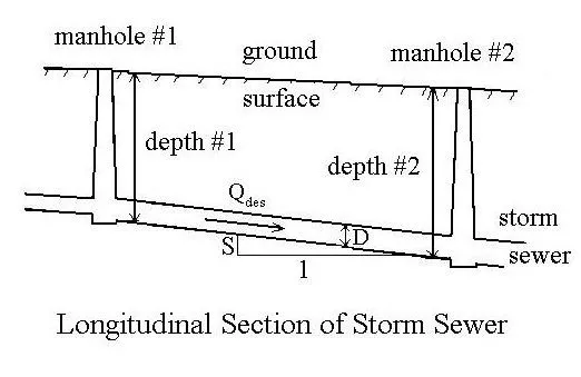
Determining Pipe Invert Depths at Manholes
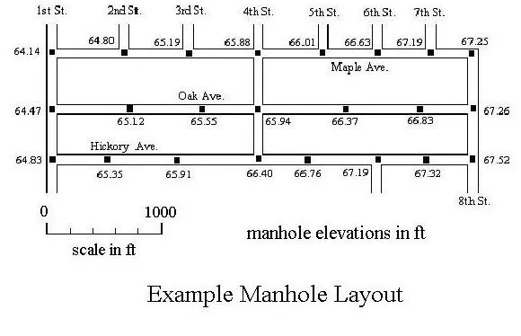
The design criterion that helps to determine the pipe invert depth (or elevation) at each manhole is a minimum required depth of cover above the sewer pipe for protection from freezing. This will typically by specified by a state or local design code. The required minimum cover, the required pipe slope, and the ground surface elevations from a map like that shown at the left, are used to calculate the pipe invert elevations at each manhole. This calculation is illustrated using Excel formulas in the Excel spreadsheet template presented in the next section, on page 2 of this article.
Use of Excel Formulas in a Spreadsheet Template to Put it all Together
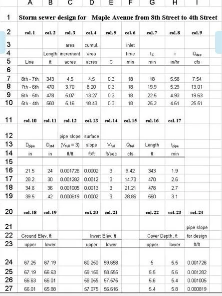
The Excel spreadsheet template shown at the left contains the design calculations for a storm sewer line along Maple Avenue, from 8th Street to 4th Street, based on the manhole layout map shown in the previous section. The column numbers given in the spreadsheet will be used to discuss the various parts of the spreadsheet calculations.
Columns 1, 2, and 3 contain information from a map that is drawn to scale, like the one in the previous section and used for this example. Column 4 is the cumulative area draining to the downstream sections of sewer pipe. In this example, the manhole at 8th Street and Maple Avenue is assumed to be the uppermost part of this sewer line. Column 3 is an estimate of the runoff coefficient. Column 3 is the inlet time from the farthest point in the drainage area. For the first section of sewer pipe, the inlet time is the time of concentration. For subsequent sections of sewer pipe, the time of concentration is the inlet time to the first inlet plus pipe flow time to the inlet of the pipe section being designed, as given in column 7.
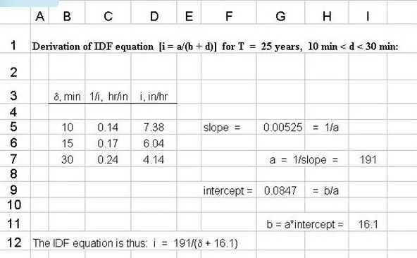
Column 8 is the calculated design rainfall intensity. The portion of the Excel template shown at the right is a linear regression of storm duration, δ, vs the inverse of storm intensity, 1/i, using I-D-F data for the location of interest, to get an equation for storm intensity as a function of storm duration. This linear regression makes use of the fact that the relationship between i and δ is typically of the form i = a/(δ + b), where a and b are constants. Column 9 is simply the calculation, Q = CiA.
Columns 10 through 15 make use of the Manning Equation and Q = VA to determine the minimum standard pipe diameter and pipe slope needed, as well as a check on Vfull and Qfull when the pipe is receiving the design stormwater runoff flow rate.
Columns 16 and 17 are used to calculate the pipe flow time to be used for the time of concentration calculation in column 7. Columns 18 and 19 give ground surface elevations taken from the manhole layout map. Columns 20 and 21 calculate the pipe invert elevations. The invert elevation of the uppermost end of the pipe is taken to be the surface elevation minus the minimum cover (5' in this case) plus the pipe diameter. The invert elevation at the lower end of the pipe section is calculated using the pipe slope that was previously determined. Columns 22 and 23 are a check on the depth of cover at each manhole, and column 24 is a listing of the final design pipe slope.