Excel Templates for Venturi and Orifice Flow Meter Calculations
Excel templates can be downloaded to use Excel formulas for venturi meter, orifice flow meter and ideal gas law calculations. The Excel formulas calculate pipe flow rates for venturi and orifice flow meters, gas density with the ideal gas law, and orifice coefficient with the ISO 5167 equation.
Orifice and Venturi Meter Calculations with Excel Spreadsheet Formulas
Excel spreadsheet formulas can be conveniently used to make calculation for differential pressure flow meters, like an orifice flow meter, a venturi meter, or a flow nozzle meter. The following sections in this article present three Excel templates for such calculations. The first Excel template is for calculating the flow rate, based on a measured pressure difference and information about the meter, the fluid, and the pipeline. In case the flowing fluid is a gas, the second Excel template allows calculation of the gas density from its molecular weight and values for the gas temperature and pressure, using the Ideal Gas Law. If the flow meter is an orifice meter with one of the ISO standard pressure tap configurations, then the third Excel template can be used to calculate a value for the orifice discharge coefficient.
Calculation of Flow Rate from Orifice, Venturi or Flow Nozzle Meter Data
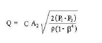
The general equation for calculating the flow rate
in a pipe from the measured pressure difference of an orifice, flow nozzle, or venturi meter is given at the left. Background information about these three types of flow meters and the parameters in the equation is available in the article, "Orifice, Venturi, and Flow Nozzle Meters for Measuring Pipe Flow Rate."
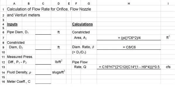
The upper image at the right shows Excel spreadsheet formulas in an Excel template for calculating the pipe flow rate
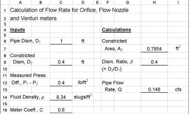
based on a measured flow nozzle, venturi, or Orifice flow meter pressure difference. This spreadsheet is suitable when a value for the fluid density is known (typically for a liquid) and a value is known for the meter coefficient, C. The lower image shows an example set of calculations using the Excel formulas in the upper image. (NOTE: You can click on the images to get a larger version that can be read better.)
Calculation of the Density of a Gas with Known Temperature and Pressure
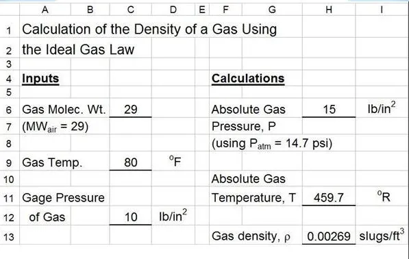
When the fluid whose flow is being measured by an orifice, flow nozzle, or venturi meter is a gas, the density is a function of both temperature and pressure, so a means of determining the density of the gas at the pipeline temperature and pressure is needed. The ideal gas law, in the form ρ = (MW)P/RT, can be used for this purpose. See the article, "Use the Ideal Gas Law to find the Density of Air at Different Pressures and Temperatures," for more details.
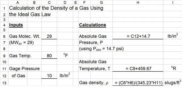
The image at the left show the Excel spreadsheet formulas to calculate gas density for specified gas molecular weight, temperature, and gage pressure. Note the the value of the Ideal Gas Law constant, R, for the units used in this Excel template is 345.25 psia-ft3/slugmole-oR. The image at the right shows an example set of calculations using the Excel formulas for air (MW = 29), temperature = 80oF, and pressure = 10 psig.
Calculation of Orifice Meter Coefficient Using ISO 5167
The meter coefficient for an orifice flow meter varies more widely with operating conditions than that of a flow nozzle or venturi meter. For an orifice meter with one of the three ISO standard pressure tap configurations (corner taps, flange taps, or D-D/2 taps) ISO 5167 provides an equation for the orifice coefficient, C, interms of the pressure tap locations, L1 and L2

;the diameter ratio, β; the pipe diameter, D1; and the pipe Reynolds number, Re. See the article, "Use ISO 5167 to Find the Orifice Discharge Coefficient for an Orifice Flow Meter," for more details about ISO 5167, the standard pressure tap configurations, and the following equation for calculating the orifice coefficient in terms of the diameter ratio, β, the pipe Reynolds number, Re, the pipe diameter, D, and pressure tap location parameters, L1 and L2:
C = 0.5959 + 0.0312 β2.1 - 0.1840 β8 + 0.0029 β2.5(106/Re)0.75 + 0.0900(L1/D)[β4/(1 - β4)] - 0.0337(L2/D)β3
The Excel formulas for calculation of the orifice coefficient are shown in the image at the left. The image at the right shows an example set of calculations using this Excel template. The calculations in the example and in the downloadable Excel templates are for "flange taps," which have L1 = L2 = 1". See the the article referenced above for more details on other pressure tap configurations.
Note that this is an iterative calculation. The Reynolds number is needed to calculate the orifice coefficient, C, but the velocity in the pipe (needed for the Reynolds number) can't be determined until C is known. The iterative approach that works well with this Excel template is to initially assume a value for the Reynolds number. A value of Re = 105 is typically a good starting point. With the assumed value for Re and values for the other input parameters shown, the orifice coefficient can be calculated and then Q and V can be calculated. The calculated value of pipe velocity, V, is then used to calculate the Reynolds number (Re = D1Vρ/μ). If the calculated value is different from the assumed value for Re, then use the calculated Re as the new assumed value and repeat the calculation. This procedure converges quite rapidly. Usually one or two iterations is all that is needed.