Material-Testing
Simple Field Testing of Materials
Most of our construction sites do not have field-testing
laboratory. In this paper simple test methods of construction materials are
described which could be performed without any machine or special equipment’s.
1. TEST FOR ORGANIC IMPURITIES IN FINE AGGREGATE
The aggregate must be checked for organic impurities such as
decayed vegetation’s, humus, and coal dust, etc. Colour test is a reliable
indicator of the presence of harmful organic matter in aggregates except in
areas where there are deposits of lignite.
Procedure:
a) Fill a 350 ml clear glass medicine bottle up to 75 ml mark
with a 3% solution of caustic soda or sodium hydroxide.
A 3% solution of caustic soda is made by dissolving 3 gm of
sodium hydroxide (which can be purchased from any local laboratory chemicals
shop) in 100 ml of clean water (preferably distilled water). The solution
should be kept in glass bottle tightly closed with a rubber stopper. Handling
sodium hydroxide with moist hands may result in serious burns. Care should be
taken not to spill the solution for it is highly injurious to clothing, leather
and other materials.
b) The representative sands sample is next added gradually until
the volume measured by the sandy layer is 125 ml. The volume is then made up to
200 ml by the addition of more of the solution. The bottle is then corked and
shaken vigorously and allowed to stand for 24 hours.
c) At the end of this period, the colour of the liquid will
indicate whether the sand contains a dangerous amount of matter or not. A
colourless liquid indicates clean sand free from organic matter. A
straw-coloured solution indicates some organic matter but not enough to be
seriously objectionable. Darker colour means that the sand contains injurious,
amounts and should not be used unless it is washed and a retest then shows that
it is satisfactory.
2. TEST FOR SILT CONTENT OF FINE AGGREGATE
It is important to use clean aggregate for concrete. If the
aggregates are coated with dirt, silt or clay, it will result in a poor
concrete because the dirt will prevent the cement from setting and also weaken
the bond between the aggregates and the cement paste.
Further owing to their fineness and therefore large surface
area, increases the amount of water necessary to wet all the particulars in the
mix, this also resulted more shrinkage of concrete. As determine with the given
field test, the sand shall not contain more than 8% of silt.
Procedure:
(a) Fill a
measuring cylinder with a representative sand (fine aggregate) sample up to 100
ml mark and add clean water up to 150 ml. To perform this test, more correctly
better dissolve a little salt in the water (1 tea spoonful to 250 ml is the
right proportion).
(b) Shake the
sample vigorously for one minute and the last few shakes being in a side wise
direction to level of the sand.
(c) Allow the
cylinder to stand for three hours during which time any silt present will
settle in a layer on the top of the sand and its thickness can be read off on
the cylinder itself. The sand shall not contain more than 8% of silt.
Note: In performing this test the sand sample should not dry.
Glass measuring cylinder capacity should be 200 ml.
3. TEST FOR MOISTURE CONTENT OF CONCRETE
AGGREGATE
The various stages in which the aggregate may exist are (a) over
dry (b) air dry (c) saturated surface dry (d) damp or moist. On the
construction site, the sand (fine aggregate) usually carries some free
moisture. Total internal moisture content of an aggregate in the saturated
surface dry condition may be termed as “Absorption capacity” although it is
sometimes referred to simply as the absorption. The amount of water required to
bring an aggregate from the air dry condition to the saturated surface dry
condition is termed as “effective absorption”. The absorption is determined by
finding the weight of a surface dried sample after it has been soaked for 24
hours and again finding the weight after the sample has been dried, the
difference in weights, expressed as a percentage of dry sample weight, is the
absorption capacity.
Procedure:
(a) Take about
one kg of representative sample of sand (fine aggregate) in a suitable size
tray. Fully immerse this sand sample in clean water for 24 hours.
(b) After 24
hours of immersion take about 500 gm of representative wet sand sample. Dry
this sand in saturated surface dry (SSD) condition either in air or heating in
a fry pan. Take the weight (A) of SSD sand sample in fry pan and dry it fully
in gentle heat. After drying take its weight (weight B).
(c) Take about
500 gm representative site sand sample. Take its weight (weight C) and fully
dry it in a fry pan. Take the dry weiht (weight D).
Calculations:
1. Water
absorption (%) = [A-B]/B x100
2. Total
moisture in site sand % = [C-D]/D x100
3. Surface
moisture in site sand (%) = Total moisture in site sand % – Absorption of site
sand %
If the result is in negative, it means the sample does not
contain any surface moisture and in it balance absorbed water is to be added to
make the site sand in SSD condition.
Note:
(A) For obtaining the
SSD condition of sand, it should be gently heated in a fry pan, mean while
stirring with a glass rod until the surface moisture disappears. This is
apparent when the sand loses its shining wet appearance and becomes dull, or
when it just attains a free running condition. The end point of aggregate SSD
condition could be found by practice. If the sand is heated beyond the SSD
condition some of the absorbed moisture will also dry and then the SSD weight
of aggregate will not be correct, and the obtained absorption result will not
be correct.
(B) The same procedure
with appropriate changes in the size of the sample and dimension of the
container may be applied to obtain moisture content of coarse aggregate.
4. TEST FOR BULKING OF SAND
Dry and fully saturated sand does not bulk. As the sand becomes
finer the bulking of the sand increases. The bulking of sand is caused by the
film of moisture which tends to keep the particles of sand apart.
Procedure
Method 1. Put sufficient quantity of site sand loosely into a
suitable conbtainer until it is about two-third full. Level off the top of the
sand and push a steel rule vertically down through the sand at the middle to
bottom, measure the height. Suppose this is `x’ cm.
Empty the sand out of the container into another container where
none of its is lost. Half fill the first
container with clean water. Put back about half the sand and rod it with a
steel rod, about 6 mm in diameter, so that its volume is reduced to a minimum.
Then add the remainder sand and level the top surface of the fully saturated
sand. Measure its depth at the middle with the steel rule suppose this is `y’
cm.
Percentage bulking =[x/y -1] x 100
Method 2. In a 250 ml measuring cylinder, pour the damp site
sand, consolidate it by staking until it reaches the 200 ml mark.
Then fill the cylinder with the clean water and stir the same
well (the water shall be sufficient to submerge the sand completely), It will
be seen that the sand surface is now below its original level. Suppose the
surface is at the mark of y ml, the percentage of bulking of sand due to
moisture shall be calculated from the formula.
Percentage bulking =[200/y -1] x
100
5. TEST FOR SPECIFIC GRAVITY OF AGGREGATE
The specific gravity of a substance is the ratio of the unit
weight of the substance to the unit weight of water. A representative aggregate
sample in SSD condition is obtained by quartering and the following weights are
used in the tests for the various sizes of aggregates.
Less than 4.75 mm : 500 to
700 gm
4.75 mm to 10 mm : 1000 to
1500 gm
10 mm to 20 mm : 1500 to 2000
gm
20 mm to 40 mm : more than
2000 gm
Procedure:
(a) Take a
suitable size jar, the top open side of which have flange, so that a glass
plate may be put on it.
(b) The jar
should be filled with clean water upto the flange and slide on it the glass
plate. If there is any air bubble, which can be seen from top of glass plate,
then the jar top should be filled with more water. There should not be any air
bubble. Take the weight of jar fully filled with water and upon it glass plate
(weight A).
2. About half empty the jar fill it with known weight of SSD
aggregate sample weight (B). As mentioned at b, fill the jar upto the top and
putt glass plate on it. There should not be any air bubble. Take its weigh
(weight C).
Specific gravity on SSD basis = B/ [B-(C-A)]
6. TEST FOR BULK DENSITY OF AGGREGATE
Bulk density is the weight of a unit volume of aggregate, usually
stated in kg per litre on room dry basis in estimating quantities of materials
and in mix computation, when batching is done on a volumetric basis.
Concrete material proportion by weight can be converted to
proportions by volume, by dividing with the bulk density of the materials
available for use at site. The bulk density of cement may be taken 1.44 kg/lit.
For determination of bulk density the container size shall be as
given below:
|
Size of particle |
Nominal capacity (litres) |
Inside dia (mm) |
Inside height (mm) |
Thickness of metal (min) (mm) |
|
4.75 mm and under |
3 |
150 |
170 |
3.15 |
|
Over 4.75 mm to 40 mm |
15 |
250 |
300 |
4.00 |
|
Over 40 mm |
30 |
350 |
310 |
5.00 |
Procedure:
(a) About 100 kg
of aggregate sample should be dried in the room.
(b) Take the
weight in kg of empty container + glass plate (Weight A).
(c) The container
is to be filled with loose sand or loose aggregate i.e. sand or aggregate
should be dropped in the container from about 5 cm height from top of
container. Take the weight of container filled with sand or aggregate + glass
plate (Weight B).
(d) Empty the
container filled it with clean water upto the top ridge putt glass plate. There
shall not be any air bubble. Take is weight (Weight C). All weight should be
taken in kg.
Loose bulk density in kg/lit on the basis
Off room dry sand or aggregate = [B-A]/[C-A]
And voids percentage = [(Specific gravity – bulk density)/
Specific gravity ] x100
7. NON-DESTRUCTIVE TESTING OF CONCRETE
STRUCTURE BY TAPPING METHOD
For testing low-grade concrete in unimportant constructions the
strength of concrete may be determined either from its hardness when scratched
with a metal “pencil” or a chisel, or from the character of the sound when
struck with a hammer, or from the character of the mark left after a hammer
blow.
The tapping method is not very exact but it is simple and can be
easily applied for an approximate determination of the strength of concrete and
in some cases is still used. On the concrete to be tested a smooth surface
about 100 x 100 mm is chosen and cleaned with a metal brush. Then a hammer
300-400 gm in mass is struck against the concrete from elbow height directly or
through a metal worker’s chisel placed at right angles to the tested surface.
The size of the mark left the hammer or the chisel and the sound of the hammer
stroke are indicative of the strength of concrete. Ten blows of average force
are made at different points on the specimen. Results, exceedingly low, are
disregarded. Approximate values of the strength of concrete obtained from these
tests are given in the following table. The tapping method is used for an
approximate determination of the strength of low-grade concrete, because the
force of the blow and the accompanying sound vary greatly depending on
subjective factors.
|
Strength of concrete N/mm2 |
Test Results |
||
|
Blow of hammer (0.4 kg) upon concrete
surface |
Blow of hammer (0.4 kg) upon chisel placed
at right angles to concrete surface |
Scratching by Chisel |
|
|
Below 6 |
Sound toneless. Deep dent with Crumbling
Edges |
Chisel is easily driven into concrete |
Concrete cut easily and crumbles |
|
6 – 10 |
Sound slightly toneless. Dent has smooth
edges. Concrete crumbles |
Chisel can be driven into concrete deeper
than 5 mm |
Visible scratches 1 – 1.5 mm deep |
|
10 – 20 |
Sound clear whitish mark remains |
Thin scales split off round the mark |
Visible scratches no deeper than 1 mm |
|
Over 20 |
Sound ringing, Metallic, Mark-visible |
Mark is not very deep |
Barely visible scratches |
8. DETERMINATION OF WEIGHT PER CUBIC METRE AND AIR CONTENT OF
FRESHLY MIXED CONCRETE
The measures for this test shall be as given below:
|
DIMENSIONL REQUIREMENTS FOR CYLINDRICAL
MEASURES |
||||
|
Nominal size of coarse Aggregate |
Nominal capacity |
Inside Dia |
Inside height |
Minimum Thickness of metal |
|
mm |
Cu.m |
Mm |
mm |
mm |
|
Upto 38 |
0.01 |
250 |
280 |
4 |
|
Over 38 |
0.02 |
350 |
285 |
5.5 |
Calibration of measure. The measure shall be calibrated by
determining the weight of water at room temperature required to fill it so that
no meniscus is present above the rim.
Accurate filling of the measure may be secured by the use of a
glass cover plate. The capacity of the measure in cubic meters shall then be
obtained by dividing the weight of water (in gms)
required to fill the measure by the unit weight of water, 1000 g/l.
Procedure:
Determination of density. The measure shall be filled with
concrete as soon as practicable after mixing. The representative sample of
concrete shall be filled into the measure in layers approximately 5 cm deep and
each layer shall be compacted by 38 cm long steel bar which shall have a
ramming face of 2.5 x 2.5 cm square. The number of strokes per layer required
to produce the specified condition will vary according to the type of concrete,
but in no case shall the concrete be subjected to less than 60 strokes per
layer for the 0.01 m3 measure or 120 strokes per layer for the
0.02 m3 measure.
The exterior surface of the cylinder shall be tapped smartly 5
to 10 times or until no large bubbles of air appear on the surface of the
compacted layer.
After consolidation of the concrete, the top surface shall be
struck-off and finished smoothly with a flat cover plate using great care to
leave the measure just level full. All excess concrete shall then be cleaned
from the exterior and the filled measure weighted.
Calculations:
1. Weight per cubic metre. The weight per cubic
metre of concrete shall be calculated by dividing the weight of fully compacted
concrete in the measure by the capacity of measure as determined above, and
shall be recorded in kg/m3.
2. Air content. The air content shall
be calculated by the formula:
A= [T-W]/T x 100
or
A = [V-VA]/V x 100
where,
A = Air content (percent of voids) in the concrete
T = Theoretical weight of the concrete, in kg/m3,
computed on an air free basis
W = Weight of concrete produced per batch in m3
V = Volume of concrete produced per batch in m3
VA= Total absolute volume
of the component ingredients in the batch, in cubic metre
The above method of calculating air content of value
particularly for air entrained concrete.
Note: The determination of the theoretical weight per cubic
meter (T) should be carried out whose value is assumed to be constant for all
batches made using identical component ingredients and proportions. It is
calculated from the formula:
T= W1/ VA
where,
T = Theoretical weight of concrete in kg/m3 computed
on an air free basis
W1 = Total weight in
kg of the component ingredient in the batch, and
VA = Total absolute
volume of the component ingredients in the batch in m3
The absolute volume of each ingredient is equal to the weight of
that ingredient divided by its specific gravity. For the aggregate components,
the bulk specific gravity and weight should be based on the saturated surface
dry condition.
For the cement, a value of 3.15 may be used unless the actual
specific gravity is determined by a recognized inert liquid method.
9. TESTING OF NON-SHRINK GROUP FOR EXPANSION
Expansion percent. As per “CORPS OF ENGINEERS SPECIFICATION FOR
NON-SHRINK GROUPS” CRD 621 83.
Apparatus:
1. 7 cm
cube mould.
2. Glass
plate of dimension 69.5 mm x 69.5 mm
3. Micrometer
Procedure:
One kg of grout is mixed with water (as per desired w/p ratio) and
poured into a bottom sealed 7 cm cube mould and height of the material is
checked (h). A glass plate is placed on the top of mix and a micrometer
head is placed on the center of the plate.
Note the initial reading.
After 24 hours check the reading of micrometer. Let the
difference in reading be (x) mm. Then,
Expansion (%) = (x/h) x100
TESTING OF FINE AGGREGATE
1. Source
of F.A. ………………………………………………………….
2. Type of
F.A. : River/crusher. Other (specify) ……………………….
3. Sieve
analysis ………………………. Date of testing ………………………
|
I.S. Sieve size |
Weight Retained (gm) |
% weight Retained |
% weight Passing |
Cumulative % weight Retained |
Remarks |
|
10 mm 4.75 mm 2.36 mm 1.18 mm 600 micron 300 Micron 150 Micron Residue |
|
|
|
|
|
|
Total= |
|
|
|
C=_______ |
|
Fineness modulus = C/100
4. Bulk density loose:
Weight of empty container + plate (a) = …………………………………kg
Weight of empty container + loose filled F.A. + plate (b)
= ………….. kg
Weight of empty container + water + plate (c) = ………………………
Kg
Bulk density loose = (b-a)/(c-a) = kg/lit
5. Specific gravity:
Weight of empty jar + water + plate (c) =
…………………………….. kg
Weight of empty jar + water + 500 gm SSD F.A. + plate (d)
=……….kg
Specific gravity = 0.500/[0.500 – (d-c)]
6. Moisture content:
(a) Water
absorption:= [(Weight of SSD sample – Oven dry
sample) / Weight of oven dry sample ] x 100
= _______________ x 100
= ………………..% water absorption
(b) Surface
moisture: [(Weight of wet sample – Weight of SSD sample)/ Weight of oven dry
sample] x 100
= _______________ x 100
= ………………..% water surface moisture.
(c) Total
moisture: = [(Weight of sample – Weight of oven dry sample) / Weight of oven
dry sample ] x 100
= _______________ x 100
= ………………..% total moisture.
TESTING OF COARSE AGGREGATE
1. Source
of C.A. ………………………………………………………….
2. Type of
C.A. : Crusher/Uncrushed…………. ……………………….
3. Maximum
size of C.A. 40/20/10 mm.
4. Sieve
analysis Date of testing ……………..
|
I.S. Sieve size |
Weight Retained (gm) |
% weight Retained |
% weight Passing |
Cumulative % weight Retained |
Remarks |
|
80 mm 40 mm 20 mm 10 mm 4.75 mm Residue |
|
|
|
|
|
|
Total= |
|
|
|
C=_______ |
|
Fineness modulus = C + 500/100 =
5. Bulk density loose:
Weight of empty container + plate (a) = …………………………………kg
Weight of empty container + loose filled C.A. + plate (b) =
………….. kg
Weight of empty container + water + plate (c) = ………………………. kg
Bulk density loose = (b-a)/(c-a) = kg/lit
6. Specific
gravity:
Weight of empty jar + water + plate (c) = …………………………….. kg
Weight of empty jar + water + 1000 gm SSD C.A. + plate (d)
=……..kg
Specific gravity = 1/ [1-(d-c)] = ………………………………
7. Moisture
content:
(d) Water
absorption:= [(Weight of SSD sample – Oven dry
sample) / Weight of oven dry sample ] x 100
= _______________ x 100
= ………………..% water absorption
(e) Surface
moisture: [(Weight of wet sample – Weight of SSD sample)/ Weight of oven dry
sample] x 100
= _______________ x 100
= ………………..% water surface moisture.
(f) Total
moisture: = [(Weight of sample – Weight of oven dry sample) / Weight of oven
dry sample ] x 100
= _______________ x 100
= ………………..% total moisture.
How do we compare Rowe cell and Oedometer apparatus?
The advantages of using Rowe cell over oedometer apparatus are:
(i) It possesses the control facilities for drainage and for the
measurement of pore water pressure.
(ii) It is capable of testing larger diameter soil samples.
Hence, more reliable data can be provided by using Rowe’s cell because of the
relatively smaller effect of structural viscosity in larger specimens.
(iii) Rowe cell uses hydraulic loading system which is less
susceptible to the effect of vibration than oedometer apparatus.
Is it worthwhile to carry out tests on particle density of soil
particles for geotechnical design?
Particle density of soils is defined by the ratio of soil
particle mass and soil particle volume. Depending on soil types, the range of
variation of soil particle density varies not significantly, i.e. by 4%.
Therefore, it may not be worthwhile to order laboratory tests and incur
additional expenditure just to determine the particles density by recognizing
that the variation of particles density is not significant.
What is the purpose of adding hydrogen peroxide in sedimentation
analysis?
There are two major techniques of particle size distribution:
(i) Sieve analysis – for soil particles larger than 60?m they can be separated by this method.
(ii) Sedimentation analysis – for soil particles smaller than 60?m, they are too small to be sieved by sieve analysis.
Instead, the particle size distribution is worked out from the rate of
settlement of soil particles suspended in water by Stoke’s law.
In sedimentation analysis, the soil under testing is firstly
boiled with little distilled water to wet and break up the particles. After
that, hydrogen peroxide is added to remove any organic material. Then the whole
mixture is allowed to stand still for a night and then boiled again to remove
hydrogen peroxide.
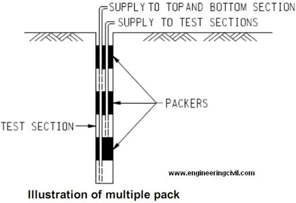
Why is multiple packer test instead of single packer test
sometimes adopted in testing permeability of rock?
Packer test is used in unlined drillholes in rock to test the
permeability. In single packer test, the hole is drilled to the bottom of first
test section and the top of the test section is sealed off by a packer. Water
is then delivered to the test section and it is kept at constant pressure and
the flow is measured.
In highly fractured rock there is a high chance that water tends
to leak around the packer which gives inaccurate result. As such, multiple
packers are adopted instead in which three sections of the drillhole are sealed
up and water is pumped to them at equal pressure. This eliminates the tendency
for water to flow around the packers from the middle section.
Hence, a more accurate result could be obtained by measuring
flow from the middle section alone.