Deoiling Hydrocyclones And Their Performance Prediction

The static hydrocyclone has rapidly been accepted as a compact and efficient means of removing dispersed hydrocarbons from water. The basic design of the static hydrocyclone is illustrated schematically in the figure below:
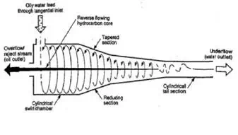
The water containing the dispersed hydrocarbons enters the hydrocyclone through a tangential inlet atthe top of the swirl chamber. As the liquids swirl along the hydrocyclone, the centrifugal forces genarated promote the separation of the hydrocarbon and water phases, with the hydrocarbon phase forming a thin core at the centre of the hydrocyclone.
By maintaining a suitable pressure ratio between the clean water outlet stream and the reject oil outlet stream, the geometry of the hydrocyclone will result in the thin hydrocarbon core flowing in a reverse direction, exiting from the top of the swirl chamber. The clean water exits from the tail section of the hydrocyclone.
The following definitions are commonly used for hydrocyclones:
Feed: The oil water stream entering the hydrocyclone
Underflow: The clean water stream exiting from the tail of the hydrocyclone
Reject Stream or Overflow: The concentrated hydrocarbon stream exiting from the head of the hydrocyclone through the reject port
Reject Ratio ®: The ratio of the reject and feed stream volumetric flow rates (R = Qreject / Qfeed)
Performance Prediction:
Cut Size Diameter:
The cut size diameter is a droplet diameter which can be used to characterize the separation performance of a hydrocyclone.
A common cut size diameter definition is the 50% cut size d50.This is defined as the hydrocarbon droplet diameter which has a 50% probability of leaving the hydrocyclone in the reject stream and a 50% probability of leaving the hydrocyclone in the water outlet stream i.e.if
nd, reject / nd,out = 1 then d = d50
Another commonly used cut size is d75, representing the hydrocarbon droplet size with a 75% chance of being removed from the water stream.
Cut Size Diameter Correlations:
Several correlations are available for the prediction of the droplet cut size. The following correlations are presented:
Bradley Equation:
d50 = 0.053*Dcycl*(ρc / (Rei*Δρ))^0.5
where:
d50 = droplet size diameter as defined above, m
Dcycl = Diameter of the cylindrical hydrocyclone chamber, m
ρc = Density of the continuous phase (water), kg/m3
Δρ = Density diff. between the continuous phase (water) (ρc) and the dispersed phase (oil) (ρoil), kg/m3
Note: The min. recommended density difference for a hydrocyclone is 50 kg/m3 @operating temperature
Rei = Di*Vi*ρc / μc
where:
Rei = Reynolds number at the hydrocyclone inlet, dimensionless
Di = inlet diameter at hydrocyclone inlet, m
Vi = Fluid velocity at inlet, m/s
μc = viscosity of the continuous phase (water), kg/m-s
Rietema Equation:
d50 = 0.51*Dcycl*[ρc / ((Rei)^1.375*Δρ)]^0.5
where:
d50 = droplet size diameter as defined above, m
Dcycl = Diameter of the cylindrical hydrocyclone chamber, m
ρc = Density of the continuous phase (water), kg/m3
Δρ = Density diff. between the continuous phase (water) (ρc) and the dispersed phase (oil) (ρoil), kg/m3
Note: The min. recommended density difference for a hydrocyclone is 50 kg/m3 @operating temperature
Rei = Di*Vi*ρc / μc
where:
Rei = Reynolds number at the hydrocyclone inlet, dimensionless
Di = inlet diameter at hydrocyclone inlet, m
Vi = Fluid velocity at inlet, m/s
μc = viscosity of the continuous phase (water), kg/m-s
Coleman-Thew Empirical Model:
d75 = (Hy75*Dcycl ^3*μc / (Q*Δρ))^0.5
where:
d75 = droplet size diameter as defined above, m
Dcycl = Diameter of the cylindrical hydrocyclone chamber, m
ρc = Density of the continuous phase (water), kg/m3
μc = viscosity of the continuous phase (water), kg/m-s
Q = Volumetric flow rate at inlet of hydrocyclone, m3/h
Δρ = Density diff. between the continuous phase (water) (ρc) and the dispersed phase (oil) (ρoil), kg/m3
Note: The min. recommended density difference for a hydrocyclone is 50 kg/m3 @operating temperature
Hy75 = c1*(ReD)^c2
where:
ReD = 4*Q*ρc / (π*Dcycl*μc)
Hy75 = hydrocyclone number, dimensionless
ReD = Hydrocyclone reynolds number, dimensionless
ρc = Density of the continuous phase (water), kg/m3
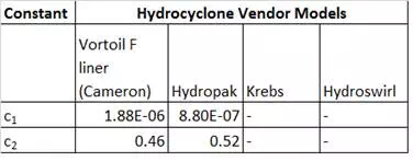
c1 & c2 = Empirically derived constants based on the hydrocyclone model
Some constants are tabulated below for some vendor models