Ancillary Electronic Equipment for Detection
The detectors used in nuclear medicine are attached to preamplifiers, amplifiers, and pulse shapers to form a signal that can be examined for information about the energy of the detected photon (Figure 13.4). The energy discriminator has lower and upper windows that are set with reference radionuclides so that typically the particular nuclide in use can be dialed in along with the width of the energy window. A photon with an energy that falls in the selected range will cause the creation of a pulse of a voltage that falls in between the levels; all other photon energies will cause voltages either too high or too low. If only gross features are being recorded, any of the instruments may be used as probe detectors and the results recorded on strip-chart recordings of activity vs. time.
The PMT “multiplies” photons (Figure 13.5) because it has a quartz entrance window which is coated to release electrons when it absorbs a light photon and there is a voltage drop; the number of electrons released is proportional to the amount of light that hits the coating. The electrons are guided through a hole and caused to hit the first dynode, which is coated with a special substance to allow it to release electrons when it is hit by an electron. There are a series of dynodes each with a voltage that pulls the electrons from the last dynodes toward it. The surface coating not only releases electrons but also multiplies the electron shower. In a cascade through 10–12 dynodes, there is a multiplication of approximately 106, so that pulses of a few electrons become currents of the order of 10–12 A. The PMTs must be protected from other influences, such as stray radioactivity or strong magnetic fields, which might cause extraneous electron formation or curves in the electron path. Without the voltage drop from one dynode to the next, there is no cascade of electrons and no counting.
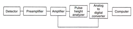
FIGURE 13.4 Schematic drawing of a generalized detector system. There would be a high-voltage power supply for the detector in an NaI(TI)-PMT detector system.
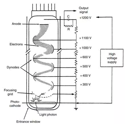
FIGURE 13.5 Schematic drawing of a photomultiplier tube (PMT). Each of the dynodes and the anode is connected to a separate pin in the tube socket. The inside of the tube is evacuated of all gas. Dynodes are typically copper with a special oxidized coating for electron multiplication.
For imaging, the x and y positions of those photons in the correct energy range will be recorded in the image because they have a Z pulse. Once the pulse has been accepted and the position determined, that position may be recorded to make an image either in analog or digital fashion; a spot may be made on an oscilloscope screen and recorded on film or paper, or the position may be digitized and stored in a computer file for later imaging on an oscilloscope screen and/or for photography. In general, the computers required are very similar to those used for other imaging modalities, except for the hardware that allows the acceptance of the pulse. The software is usually specifically created for nuclear medicine because of the unique needs for determination of function.
The calibration of the systems follows a similar pattern, no matter how simple or complex the instrument. Most probe detectors must be “peaked,” which means that the energy of the radioactivity must be connected with some setting of the instrument, often meant to read in kiloelectronvolts. This is accomplished by counting a sample with the instrument, using a reasonably narrow energy window, while varying the high voltage until the count rate reading is a maximum. The window is then widened for counting samples to encompass all the energy peak being counted. The detector is said to be liner if it can be set with one energy and another energy can be found where it should be on the kiloelectronvolt scale.
To ensure that the images of the radioactivity accurately depict the distribution in the object being imaged, the system must be initialized correctly and tested at intervals. The several properties that must be calibrated and corrected are sensitivity, uniformity, energy pulse shape, and linearity. These issues are addressed in several ways. The first is that all the PMTs used in an imaging system must be chosen to have matched sensitivities and energy spectra. Next, during manufacture, and at intervals during maintenance, the PMTs’response to voltage is matched so that the voltage from the power supply causes all the tubes to have maximum counts at the same voltage. The sensitivities of all the tubes are also matched during periodic maintenance. Prior to operation, usually at the start of each working day, the user will check the radioactive peak and then present the instrument with a source of activity to give an even exposure over the whole crystal. This uniform “flood” is recorded. The image may be used by the instrument for calibration; recalibration is usually performed at weekly intervals. The number of counts needed depends on the use the instrument is to be put to, but generally the instrument must be tested and calibrated with numbers of counts at least equal to those being emitted by the patients and other objects being imaged.
Because the PMT placement means that placement of the x and y locations is not perfect over the face of the crystal but has the effect of creating wiggly lines that may be closer together over the center of the PMT and farther apart at the interstices between tubes, the image may suffer from spatial nonlinearity. This can be corrected for by presenting the system with a lead pattern in straight-line bars or holes in rows and using a hard-wired or software method to position the X and Y signals correctly. This is called a linearity correction. In addition, there may be adjustments of the energy spectra of each tube to make them match each other so that variations in the number of kiloelectronvolts included in the window (created by varying the discriminator settings) will not create variations in sensitivity. This is called an energy correction.