Various Detector Configurations
The detectors in clinical nuclear medicine are NaI(TI) crystals. In research applications, other substances are employed, but the engineering considerations for the use of other detectors are more complex and have been less thoroughly explored (Table 13.3).
The possibilities for configuring the detectors have been increasing, although the older methods tend to be discarded as the new ones are exploited (see Table 13.2). This is in part because each laboratory cannot afford to have one of every kind of instrument, although there are tasks for which each one is ideally suited.
The first instruments possible for plane-projection imaging consisted of a moving single crystal probe, called a rectilinear scanner. The probe consisted of a detector (beginning with NaI(TI) but later incorporating small semiconductors) that was collimated by a focused lead collimator of appreciable thickness (often 2 in. of lead or more) with hole sizes and thicknesses of septa consonant with the intended energy and organ size and depth to be imaged. The collimated detector was caused to move across the patient at a constant speed; the pulses from the detector were converted to visible signals either by virtue of markings on a sheet or of light flashes exposing a film. This detector could see only one spot at a time, so only slow temporal changes in activity could be appreciated. A small organ such as the thyroid could be imaged in this fashion very satisfactorily. Bone imaging also could be done with the later versions of this instrument.
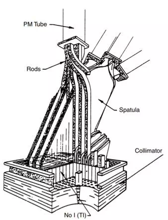
FIGURE 13.1 The Bender–Blau autofluoroscope is a multicrystal imager with a rectangular array of crystals connected to PMTs by plastic light guides. There is a PMT for each row of crystals and a PMT for each column of crystals, so an N by M array would have (N + M) PMT
To enlarge the size of the detector, several probes, each with its own photomultiplier tube and collimator, could be used. Versions of this idea were used to create dual-probe instruments to image both sides of the patient simultaneously, bars of probes to sweep down the patient and create a combined image, etc.
To go further with the multiple crystals to create yet larger fields of view, the autofluoroscope (Figure 13.1) combined crystals in a rectangular array. For each to have its own photomultiplier tube required too many PMTs, so the instrument was designed with a light pipe to connect each crystal with a PMT to indicate its row and a second one to indicate its column. The crystals are separated by lead septa to prevent scattered photons from one crystal affecting the next. Because of the large number of crystals and PMTs, the instrument is very fast, but because of the size of the crystals, the resolution is coarse. To improve the resolution, the collimator is often jittered so that each crystal is made to see more than one field of view to create a better resolved image. For those dynamic examinations in which temporal resolution is more important than spatial resolution, the system has a clear advantage. It has not been very popular for general use, however. In its commercial realization, the field of view was not large enough to image either lungs or livers or bones in any single image fashion.
As large NaI(TI) crystals became a reality, new ways to use them were conceived. The Anger camera (Figure 13.2) is one of the older of these methods. The idea is to use a single crystal of diameter large enough to image a significant part of the human body and to back the crystal by an array of photomultiplier tubes to give positional sensitivity. Each PMT is assigned coordinates (Figure 13.3). When a photon is absorbed by the crystal, a number of PMTs receive light and therefore emit signals. The X and Y signal values for the emanation are determined by the strength of the signal from each of the tubes and its x and position, and the energy of the emanation (which determines if it will be used to create the image) is the sum of all the signals (the Z pulse). If the discriminator passes the Z pulse, then the X and Y signals are sent to whatever device is recording the image, be it an oscilloscope and film recording system or the analog-to-digital (A/D) converters of a computer system. More recently, the A/D conversion is done earlier in the system so that the X and Y signals are themselves digital. The Anger camera is the major instrument in use in nuclear medicine today. It has been optimized for use with the 140-keV radiation from Tc-99m, although collimators have been designed for lower and higher energies, as well as optimized for higher sensitivity and higher resolution. The early systems used circular crystals, while the current configuration is likely to be rectangular or square.
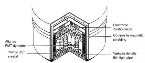
FIGURE 13.2 Anger camera detector design. This figure shows a cross section through the camera head. The active surface is pointed down. Shielding surrounds the assembly on the sides and top.
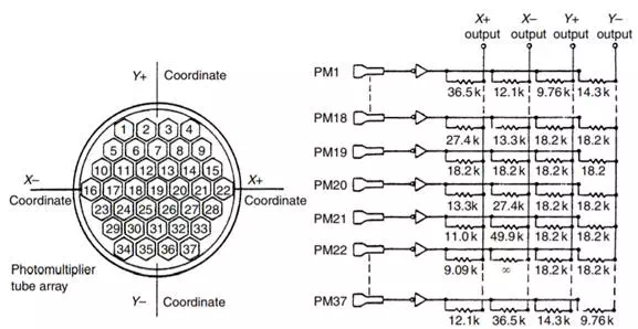
FIGURE 13.3 An array of PMTs in the Anger camera showing the geometric connection between the PMTs and the X and Y output.
A combination of the Anger positional logic and the focused collimator in a scanner produced the PhoCon instrument, which, because of the design of its collimators, had planar tomographic capabilities (the instrument could partially resolve activity in different planes, parallel to the direction of movement of the detector).