Gradient Coils
Three gradient fields, one each for the x, y, and z directions of a Cartesian coordinate system, are used to code position information into the MRI signal and to permit the imaging of thin anatomic slices [Thomas, 1993]. Along with their larger size, it is the use of these gradient coils that distinguishes MRI scanners from the conventional NMR systems such as those used in analytical chemistry. The direction of the static field, along the axis of the scanner, is conventionally taken as the z direction, and it is only the Cartesian component of the gradient field in this direction that produces a significant contribution to the resonant behavior of the nuclei. Thus, the three relevant gradient fields are Bz = GxX, Bz = GyY , and Bz = GzZ. MRI scans are carried out by subjecting the spin system to a sequence of pulsed gradient and RF fields. Therefore, it is necessary to have three separate coils — one for each of the relevant gradient fields — each with its own power supply and under independent computer control. Ordinarily, the most practical method for constructing the gradient coils is to wind them on a cylindrical coil form that surrounds the patient and is located inside the warm bore of the magnet. The z gradient field can be produced by sets of circular coils wound around the cylinder with the current direction reversed for coils on the opposite sides of the magnet center (z = 0). To reduce deviations from a perfectly linear Bz gradient field, a spiral winding can be used with the direction of the turns reversed at z = 0 and the spacing between windings decreasing away from the coil center (Figure 12.10). A more complex current pattern is required to produce the transverse (x and y) gradients. As indicated in Figure 12.11, transverse gradient fields are produced by windings which utilize a four-quadrant current pattern.
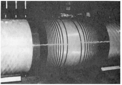
FIGURE 12.10 Z-gradient coil. The photograph shows a spiral coil wound on a cylindrical surface with an overwiding near the end of the coil. (Courtesy of R.J. Dobberstein, General Electric Medical Systems. Reprinted with permission from Schenck and Leue, 1991.)
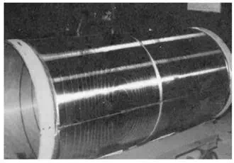
FIGURE 12.11 Transverse gradient coil. The photograph shows the outer coil pattern of an actively shielded transverse gradient coil. (Courtesy of R.J. Dobberstien, General Electric Medical Systems. Reprinted with permission from Schenck and Leue, 1991.)
[Edelstein et al., 1980] utilizes a slice-selection gradient pulse to select the spins in a thin (3–10 mm) slice of the patient and then applies readout and phase-encoding gradients in the two orthogonal directions to encode two-dimensional spatial information into the NMR signal. This, in turn, requires that the currents in the three gradient coils be rapidly switched by computer-controlled power supplies. The rate at which gradient currents can be switched is an important determinant of the imaging capabilities of a scanner. In typical scanners, the gradient coils have an electrical resistance of about 1 Ὠ and an inductance of about 1 mH, and the gradient field can be switched from 0 to 10 mT/m (1 G/cm) in about 0.5 msec. The current must be switched from 0 to about 100 A in this interval, and the instantaneous voltage on the coils, L di/dt, is on the order of 200 V. The power dissipation during the switching interval is about 20 kW. In more demanding applications, such as are met in cardiac MRI, the gradient field may be as high as 4–5 mT/m and switched in 0.2 msec or less. In this case, the voltage required during gradient switching is more than 1 kV. In many pulse sequences, the switching duty cycle is relatively low, and coil heating is not significant. However, fast-scanning protocols use very rapidly switched gradients at a high duty cycle. This places very strong demands on the power supplies, and it is often necessary to use water cooling to prevent overheating the gradient coils.