Ultrasound Imaging
Introduction
1. The application of ultrasound in medical field is based on the sonar principle as used by bats, ships at sea and anglers with fish detectors. It is totally non-invasive procedure. Acoustic waves are easily transmitted in water, but they are reflected from an interface according to the change in the acoustics impedance. Leaving bones and lungs, all tissues of our body are composed of water which can transmit acoustic waves easily. Ultrasound can be used for obtaining images of internal organs by sending high frequency sound waves into the body. The reflected sound waves (returning echoes) are recorded and processed to reconstruct real time visual images by the computer. The returning sound waves (echoes) reflect the size and shape of the organ and also indicate whether the organ is solid, fluid or something in between. Unlike x-rays, ultrasound requires no exposure to ionization radiation. It is also a real time technique that can produce a picture of blood flow as it is at the very moment of imaging.
Ultrasound Wave
1. The human can hear sound in the frequency range of 20 hertz to 20,000 hertz. As the name suggests, ultrasound has frequency greater than 20,000 hertz. Diagnostic ultrasound has the range of 1 to 10 megahertz. Ultrasound travels in the form of longitudinal wave i.e., the particles of the medium move in same direction in which the wave propagates. The wave transfers energy through the motion of regions of compression and rare fraction within the wave. The propagation of wave depends upon the elastic properties of the medium. If pressure change is ∆P and ∆V/V is corresponding change in the volume of the medium, than

where β = modulus of elasticity. The average speed of wave in biological tissues is given by relation

where
 = density
of the medium without disturbance.
= density
of the medium without disturbance.
The average speed in tissue is taken as 1540 m/sec.
2. The velocity of ultrasound in a medium depends upon modulus of elasticity and density of the medium. The knowledge of velocity in a medium is essential in calculating the depth to which a wave has potential to traverse before it is reflected. The depth of penetration is the product of velocity and time lapsed for the wave to travel from source to interface and back. As the ultrasound beam encounters tissues of different acousitc impedance, velocities are altered such that returning echoes are received by the receiver at different times and echocs have different intensities. The differences in time and intensity have useful information. This information as well as the knowledge about velocity in the tissue are used by the computer to generate the image on the monitor. Transmit power or intensity is manually adjustable in the machine. Ultrasound power is expressed by decible (db).
Scanning
1. General rules of scanning are : (1) ultrasound beam should be directed perpendicular to the object of interest for optimal visualisation (2) the transducer must be selected which has the highest frequency allowable for the penetration required (3) a full bladder is required for optimal visualization of the uterus and ovaries (GYN) and (4) scanning of all organs of interest is to be done in two planes which are perpendicular to each other. The scanning modes are : (1) bistable scanning (2) Grey scale imaging (3) A mode (4) B-mode (5) M-mode and (6) real time. Bistable scanning displays images in black and white. Grey scale imaging is commonly used in which an analog to digital scan converter transfers information from the receiver to the computer. Multiple shades of grey enhance tissue characteristics and make the ultrasound image more aesthetic and realistic. Human eye can discern upto 32 shades of grey. Therefore most systems employ 32 shades of grey only. A-mode (amplitude mode) displays the amplitude of individual echoes as a function of distance or time on cathode ray tube. The display is shown alongside the image which is helpful in determining the type of tissue i.e., cystic or solid. B mode (Brightness mode) displays echoes as individual spots on the screen corresponding to the points of origin in the tissue. Differences in amplitudes of returning echoes manifest as different brightness of the dots. Using many pixels (picture elements), these numerous dots can be arranged in such a way as to appear in different shades of grey for good visualisation. A schematics block diagram of a B-mode ultrasound imaging system is as shown in the figure. M-mode (motion mode) is nothing but the application of B-mode to a moving structure varying with time. Real time imaging allows the processing of the grey scale characteristics and the motion of interfaces. The brightness dots move on the monitor screen as the actual interfaces Echocardiogram gives the movement of valves and other structures of the heart which are displayed as a function of time. M-mode technique is used to obtain it. Amode is used for echoencephalogram which can determine the location of the problem of the brain. B-mode is used for diagnostic scanning of the eye. B-mode is also used for visualizing various organs and stuctures of human body which include breasts, kidneys, ovaries and tubes. It permits examination of foetus as early as the 4-week stage.

The Ultrasound Transducer
1. The transducer is a device capable of changing one form of energy into another. In ultrasound, the transducer is both sender and receiver of ultrasound pulses and echoes. The transducer converts electrical impulses into ultrasound waves and vice versa. Generally a piezoelectrical crystal is used to create the ultrasound waves. As the receiver, the transducer has many functions like amplification, compensation, demodulation, compression and rejection. Man-made lead zirconate and lead titanate are also used as transducer. The electricity is applied to the transducer at a specific pulse rate which allows waves to travel and echo back to the receiver. The transducer sends pulse of one microsecond duration with the interval of 999 microseconds before sending next pulse. Hence the ultrasound scan head is in the “listening” mode for the echoes for most of the time. The beam emitted by the transducer has two fields viz. near field and far field. Near field has width from the transducer’s face to the focal point beyond which the beam diverges and is called far field. Due to divergence, resolution region is bad in the far field as compared to the near field.
Image Resolution
1. Resolution is the ability of the system to separate and define small and closely separated structure. The resolution can be: (1) lateral and (2) axial. Lateral resolution is the ability of the system to separate and define small structures in the plane perpendicular to the beam axis. Lateral resolution can be optimised by focussing the beam at the area of interest and then slowly increasing the frequency. If the beam width is greater than the separation between two objects then these objects can not be resolved. Axial resolution is the measure of the system to separate and define structures along the axis of the beam. It depends upon the pulse duration. Two neighbouring structures can be resolved by beam if the wavelength of the beam is less than their axial distance between them. However the average ultrasound pulse contains two wave lengths. Therefore higher frequency transducer has to be used to improve the axial resolution. The frequency cannot be made much higher to have better resolution as then the penetration of wave falls with increased frequency.
Working Of Ultrasound
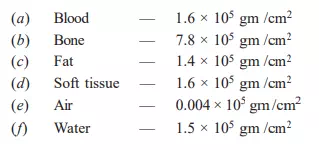
1. The ultrasound image is formed from the useful information contained by the echoes of the ultrasound which are reflected back while traversing and interacting with the tissues of the body. These interaction contributes to image formation and images vary as the tissues vary themselves. It is important to have known values of acoustic impedance (z) and speed of ultrasound in the particular tissue. The acoustic impedance is a function of the elasticity and density of a particular tissue. Materials with high acoustic impedance can transmit sound faster than others. The acoustic impedance of some materials are :
2. The ultrasound beam is attenuated while traversing through the tissues. The beam may be partly scattered, reflected, refracted or absorbed. The amount of intensity removed from the beam per unit depth is expressed as the attenuation coefficient
 which is a logarithmic
expression of the ratio of intensity of the returning echoes to the intensity
of the original sound beam. As frequency increases, the attenuation coefficient
also increases. The beam is generally attenuated one dB per mhz and per cm of
tissue traversed. When the beam reaches perpendicular to the tissue interface
within the body, the energy is reflected back towards the transducer cum
receiver. The amount of energy reflected is proportional to the difference in
acoustic impedance between the structures forming the tissue interface. These
echoes are manipulated for the reconstruction of the diagnostic image. 3.
Another reason of the loss of beam energy is absorption by the way of heat. In
order to visualise internal structure, some form of compensation has to be
employed. The difference in the intensity and amplitude of returning ehocs are
compensated by the methods known as time gain compensation and depth gain
compensation. On application of these compensation, equal amplitudes of echoes
are displayed for the tissues having same impedances irrespective of the depth
traversed or time elapsed between pulse transmission and listening of echo.
which is a logarithmic
expression of the ratio of intensity of the returning echoes to the intensity
of the original sound beam. As frequency increases, the attenuation coefficient
also increases. The beam is generally attenuated one dB per mhz and per cm of
tissue traversed. When the beam reaches perpendicular to the tissue interface
within the body, the energy is reflected back towards the transducer cum
receiver. The amount of energy reflected is proportional to the difference in
acoustic impedance between the structures forming the tissue interface. These
echoes are manipulated for the reconstruction of the diagnostic image. 3.
Another reason of the loss of beam energy is absorption by the way of heat. In
order to visualise internal structure, some form of compensation has to be
employed. The difference in the intensity and amplitude of returning ehocs are
compensated by the methods known as time gain compensation and depth gain
compensation. On application of these compensation, equal amplitudes of echoes
are displayed for the tissues having same impedances irrespective of the depth
traversed or time elapsed between pulse transmission and listening of echo.
Ultrasound Machine
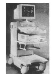
1. A bed side ultrasound machine is about the size of a small cupboard as shown in the figure. It consists of a computer with a display unit, circuitry and a hand-held transducer. The transducer has the shape of a microphone. It is meant to send out the ultrasound beam and to receive the reflected sound waves. The reflected sound waves are fed to a computer which with the help of algorithms, process them to create the images.
Doppler Ultrasound
1. Doppler ultrasound is based on the principle that sound reflected by a moving target like blood has a different frequency from the incident sound wave. The difference in frequencies is known as Doppler shift which is proportional to the velocity of the target. Doppler shift is the useful information with the echoes which helps in the detection of flowing blood. It also enables to quantify the velocity of the blood. It is possible to give colour coding to the doppler information and superimpose it on a real time B-mode image facility which can help in identification of blood vessels or blood vessels having abnormal flow. This technique can also be used to diagnose coronary stenosis.
Advantages Of Ultrasound
1. Ultrasound is relatively inexpensive and non-invasive. It does not expose patients to ionizing radiation and hence it is safe. It is preferred for children and pregnant women. The machine is also comparatively inexpensive.
Disadvantages Of Ultrasound
1. Ultrasound imaging system is highly operator dependent. It cannot be used for full body survey. It cannot image air containing organs or bones. The resolution of the ultrasound image is inversely related to the depth of penetration. The quality of image decreases in the case of obese patients.