Types of Suspension Systems
Even though there are many different suspension setups, most types can be categorized into one of these types: MacPherson strut, modified strut, multilink, short/long arm, I-beam, and solid axles. Regardless of the type, all suspensions try to accomplish the same goals of good ride quality and handling.
Macpherson Struts
The popularity of small FWD vehicles has brought with it the dominate type of suspension system used today, the MacPherson strut suspension. These systems combine a coil spring, shock absorber, and bearing plate into a single unit. A typical strut is shown in Figure 6-32.
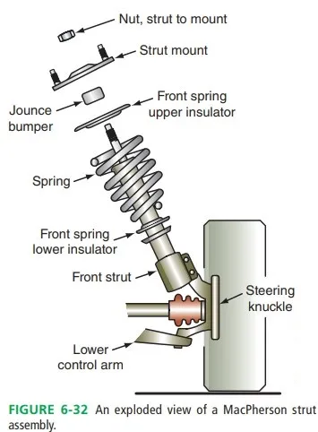
This arrangement allows for greater engine compartment space and reduced weight compared to short/long arm suspensions. This is because the MacPherson strut suspension eliminates the upper control arm and upper ball joint. This reduces weight and moves the top of the suspension higher and toward the outside of the vehicle. Because the upper control arms are removed, there is space for the engine and transmission to be mounted transversely (sideways) in the engine compartment.
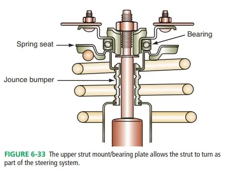
The strut connects to the car body through the upper strut mount or bearing plate, which also acts as a pivot and damper. The upper mount provides flexibility, so the strut can change angle to follow the path of the lower ball joint. The mount also dampens or reduces vibration and serves as the upper pivot for the steering axis. The components of a strut mount are illustrated in Figure 6-33.
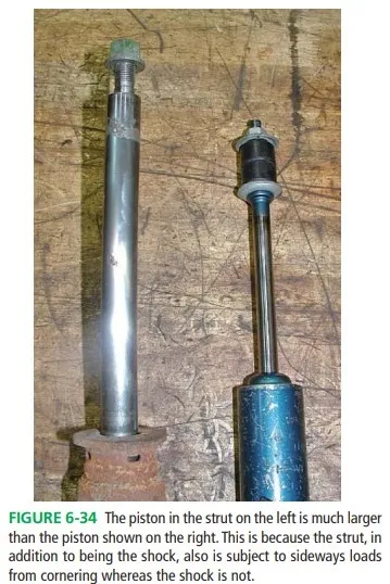
The shock absorbers piston rod in a strut is larger than the standard shock piston rod to withstand sideways bending from loads placed on the tire while it is turning. Figure 6-34 shows a comparison of a strut piston and a shock piston. The strut piston rod, on the left, is much larger in diameter than that of the shock, shown on the right.
Modified Struts
Some vehicles use a strut-style shock absorber but relocate the spring. These are not true MacPherson struts. Called a modified strut, this system has the spring mounted separate from the strut. The strut performs the function of the shock absorber and is connected to an upper bearing plate at the top and to the steering knuckle at the lower end. The coil spring is located between the frame and the lower control arm. This design has the weight and space saving advantages of the MacPherson strut suspension but can contain larger springs. Relocating the spring also can allow for a wider distance between the wheel wells, increasing engine compartment room.
Multilink
Many vehicles use a multilink system. With a multilink suspension, the steering knuckle is taller than on a traditional strut or short/long arm suspension, often reaching the height of the top of the tire. The strut does not turn with the steering axis; rather it is mounted rigidly to the body at the upper strut mount. This is because the steering knuckle pivots on the upper and lower ball joints for steering action. Multilink systems are designed to produce neutral steering on FWD vehicles, which tend to exhibit understeer with traditional MacPherson strut suspensions. This suspension is also commonly used on RWD cars, light trucks, and SUVs.
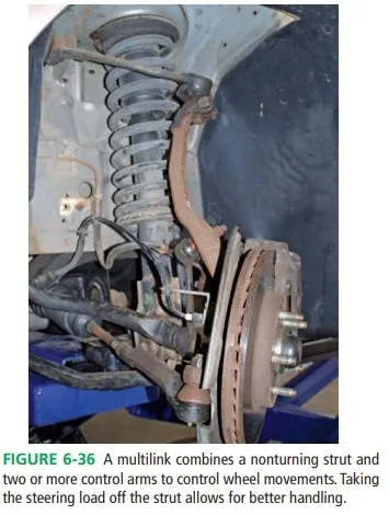
Figure 6-36 shows a common multilink arrangement. Multilink suspensions are also found on the rear of many vehicles, both FWD and RWD. Several control arms are used to reduce rear axle movements and provide better handling and ride qualities than a traditional rear strut system.
Short/Long Arm
Short/long arm suspensions, also called SLA suspensions, are typically used on RWD vehicles. This suspension consists of two unequal length control arms connected with a steering knuckle. The control arms are generally triangular and are often called wishbones or A-arms. A steering knuckle, control arm bushings and ball joints comprise the rest of the suspension.
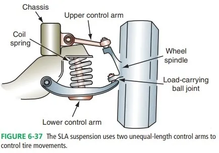
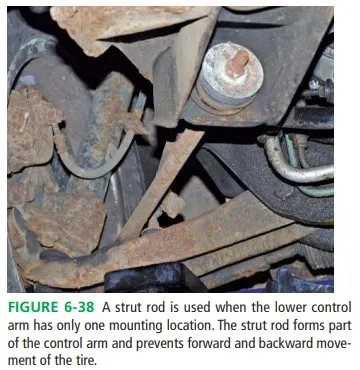
Figure 6-37 shows an illustration of a typical system. Control arm design is matched with the spring for tire control and ride characteristics. The control arms are mounted to the frame with control arm bushings. Some suspensions use a lower control arm with a single frame mounting point. In this case, a strut rod will also be used as an additional mount and stabilizer for the control arm as shown in Figure 6-38.
SLA systems use two ball joints, one of which carries the sprung weight of the vehicle. The other ball joint provides a friction and pivot point and does not carry weight. The load-carrying joint is located in the control arm in which the spring sits. The other ball joint is called the friction or following ball joint.
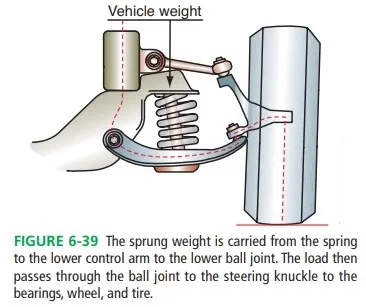
Figure 6-39 shows how the weight is carried by the load-carrying ball joint in an SLA suspension. SLA suspensions are not as common as they once were due to the popularity of FWD vehicles. These suspensions tend to intrude into the engine compartment, causing space problems with FWD drivetrains.
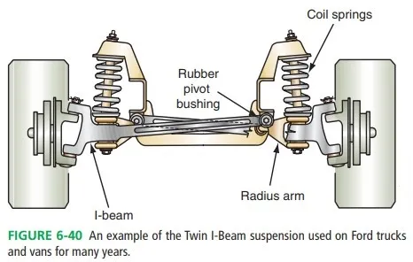
I-BEAM
This suspension system was used on Ford trucks and vans for many years. Twin I-beams are strong and simple like solid axles but provide independent movement of the front suspension. An illustration of this system is shown in Figure 6-40. I-beams are mounted to the crossmember with a bushing and house the ball joints at the outside of the beam. I-beams also use a radius arm to control I-beam movement, as shown in Figure 6-41. I-beams are similar to very long control arms. They move on a pivot and allow for vertical wheel movement while the radius arm stops forward and backward movement of the suspension.