Introduction toDesign, Optimization and Modelling of High Power Density Direct-Drive Wheel Motor for Light Hybrid Electric Vehicles
Recent environmental concerns due to global warming and air pollution motivated many countries around the world to legislate fuel economy and emission regulations for ground vehicles [1]. Furthermore, the necessity of developing alternative methods to generate energy for vehicles owing to depletion of conventional resources was greater than ever [2]. These features encouraged the introduction of fuel cell vehicles (FCVs), electric vehicles (EVs) and hybrid electric vehicles (HEVs) as suitable candidates for the replacement of the conventional internal combustion engine counterparts. Since the performance of EVs and FCVs is still far behind the requirements, HEVs are considered as the most reliable and preferred choice among similar technologies by manufacturers, governments and consumers [3, 4]. Comparing to those technologies, HEVs are advantageous, as they exhibit high fuel economy, lower emissions, lower operating cost and noise, higher resale price, smaller engine size, longer operating life and longer driving range [5]. The world HEVs market has been rapidly growing and existing hybrid powertrains include passenger cars, small, medium and heavy trucks, buses, vehicles used in construction domain (e.g. forklifts, excavators), etc.
Despite HEVís high performance, their design and control strategies are not trivial. Multiple hybrid electric architectures have been developed and incorporated so far into commercially available vehicles in order to find acceptable design solutions with respect to various objectives and constraints [6]. Each configuration presents particular characteristics and the architecture selection depends on the application requirements and vehicleís type. For instance, series configuration is mainly used in heavy vehicles, whereas parallel-series one is preferable in small and medium automobiles, such as passenger cars and smaller buses, notwithstanding its more complex structure [7]. The specific topology combines the advantages of both series and parallel HEVs and has a greater potential in improving fuel economy and efficiency of the overall powertrain [8]. The HEV performance is even more enhanced when new design methodologies are implemented in order to find optimal configurations for power split devices, whereas at the same time, a single planetary gear is used [1].
However, the performance of an HEV is strictly dependent on the individual characteristics of its components (i.e. the internal combustion engine, the electrical motor and generator, the electronic equipment, the batteries, etc.). There is a strong ďconnectionĒ among them and their collaboration interacts with the performance of the vehicle [9]. Several techniques, presented in [10], can be applied in order to achieve the optimal design and energy management of an HEV. According to [11], multi-objective optimization procedure and decision-making approach are necessary since there is a great amount of variables and goals to be taken into account. Moreover, among the most crucial decisions in the design of a HEV is the selection of the electric motorís type and its topology. A large amount of requirements such as (a) high power and torque density, (b) flux-weakening capability, (c) high efficiency over a wide range of speed, (d) high fault tolerance and overload capability, (e) high reliability and robustness, (f) low acoustic noise during operation and (g) low cost have to be met if a motor is to be considered as a suitable one for such an application [4].
Nowadays, various structures have been tested by HEV manufacturers and even more have been investigated in recent studies, e.g. [12]. Some of them, such as switched-reluctance motors (SRMs), despite their important advantages (high fault tolerance, simple construction, outstanding torque-speed characteristics and low cost) are currently not widely used for HEV applications. This is associated with the fact that they exhibit high acoustic noise, high torque ripple and low power factor [13]. Among the most popular topologies for this kind of traction system are induction and permanent magnet synchronous motors [14]. These two types are thoroughly examined and compared to each other [15] and their specific features are quite well known so far [16].
In order to meet the continuously increasing power density and efficiency requirements, PMSMs have become the dominant topology for light duty HEVs [14]. PMSMs with one or multiple layers of interior magnets fulfil the aforementioned characteristics and are commonly used in several commercial HEVs. Their typical output power varies from 30 to 70 kW for full hybrid passengers cars and can exceed 120 kW in the case of sport utility vehicles (SUVs). Recently, it has been found that surface-mounted permanent magnet synchronous motors (SPMSMs), especially when they are combined with concentrated windings instead of distributed ones, are also promising candidates for HEV propulsion [16]. They present high efficiency, satisfactory flux-weakening capability, low cogging torque and facile manufacturing procedure [17]. Honda Insight was one of the first commercial HEVs that incorporated this specific motor configuration. Since then, there has been increasing research interest for this topology.
That research effort though was carried out mainly for inner rotor topologies, in which the propulsion is provided by a single traction motor coupled with a gearbox and a differential. Thus, the perspective of mounting a motor with outer rotor to the wheel of a vehicle is very interesting and may present plenty of advantages. In this case, much lower flux density and respectively less magnet mass is required for the achievement of the same maximum torque. Copper as well as mechanical losses can be significantly lower than the corresponding ones of inner rotor topology. The manufacturing cost is lower, whereas at the same time, the total structure is lighter and can be constructed more easily [18]. Numerous in-wheel concepts for HEVs have been developed in the last years, mainly by Protean Electric and Mitsubishi.
The design procedure of direct-drive SPMSMs for an HEV presents increased complexity. There is a large number of variables and geometrical parameters that have to be estimated, while simultaneously numerous problem constraints have to be satisfied. The applied constraints refer to the maximum acceptable value of current density, the maximum value of dc-link voltage, the motorís volume and weight due to the limited available space, etc. Additionally, SPMSMs have to exhibit low-current harmonic content, non-saturable operation, low torque ripple and cogging torque. The determination of motorís thermal behaviour during different operating conditions and the implementation of the suitable cooling system are also of great importance. The adequate temperature alleviation can ensure the high driving performance, the motorís durability and the elimination of magnets demagnetization risk [19].
Based on the above, this chapter aims to investigate, optimize, compare and propose suitable high-power density in-wheel SPMSMs for a light HEV application. For this purpose, a design, optimization and modelling methodology for in-wheel motors is analytically presented in Section 2. According to this approach, the specifications of the derived topology are incorporated to an analytical HEVís model, which has been developed in Matlab/Simulink. In this way, the better approximation of the dynamic behaviour of the entire system is allowed. The performance estimation of each single subsystem and the calculation of parameters, such as the fuel consumption during different driving cycles, are also far more accurate. This methodology is compared to so far commonly used techniques, which are reviewed here too. Next, the proposed approach is applied to the case of two 15.3 kW in-wheel motors, which are going to be part of the driving system of a hybrid passenger car with series-parallel configuration. The derived results are given in Section 3 and relevant discussion is made regarding the motor and overall HEV system performance. Moreover, motors thermal behaviour is studied and a simple and effective cooling system for this kind of traction system is proposed. Finally, Section 4 summarizes and concludes the work.
High-power density direct-drive in-wheel motors
REQUIREMENTS OVERVIEW
The development of a direct-drive SPMSM, which will exhibit desirable performance, requires a large amount of problem variables, constants and constraints to be taken into account according to [20]. Moreover, meta-heuristic optimization techniques can be applied along with the classical design theory and the analytical equations. In this case, the multi-objective SPMSM optimization has to be modelled and performed carefully, especially when certain quantities are of primary concern [21]. The problem complexity is increased if an in-wheel PMSM is supposed to be incorporated into the powertrain of an HEV, whereas its operating point varies almost ceaselessly. Thus, the study of motor performance in the rated operating point or in the point of maximum provided torque, using finite element method (FEM) or fixed permeability method (FPM) has been proven inefficient enough [22]. Consequently, various design approaches and optimization methodologies have been revealed so far and each of them has its own advantages and disadvantages.
In classical HEV design process motorís efficiency map or torque-speed curve is a convenient way to represent drive systemís performance. The determination of efficiency, torque and speed for different operating points permits the preliminary estimation of motorís characteristics in agreement with vehicleís attribute. Also, different topologies that are investigated as possible candidates for the same application can be easily compared to each other [23]. However, by using efficiency maps the motor is considered as a black box, which responds to certain inputs (voltage and current). These two variables are assumed to be optimal in order to achieve the highest efficiency at a specific torque and speed output. Furthermore, a map scaling factor model (MSFM), based again on the knowledge of an efficiency map, is generally used for the selection of motorís output power rating and specifications. The efficiency and torque are scaled using a linear dependency on the rated power. At the same time, few HEVís subsystems, such as the internal combustion engine, wheels, batteries and control scheme, can also be modelled constructing the appropriate equations and then a joint optimization of all the subsystems using dynamic programming can be performed [24].
Although the aforementioned procedure permits a better interaction between the electric motor/s and the other vehicleís subsystems, the approximation of the dynamic behaviour of the entire system is not satisfactory enough. It lacks accuracy concerning energy management estimation and fuel consumption calculation. Additionally, there is no association between motorís performance and its geometrical parameters. A compromise between FEA and MSFM method is introduced in [9], in which the detailed magnetic circuit model is incorporated in the optimization process. Starting from a preliminary topology, the final configuration can be derived when the userís requirements are met. The drawback of this approach is that only a restricted number of variables can be treated simultaneously. Thus, some geometrical parameters, such as motorís diameter and length, should be specified by the designer and this method should be applied only for the optimization of magnets and windings modulation. A fast magnetostatic FEA is proposed in [25] in order to address the specific problem. The derived results are now more precise and the computational time and complexity are significantly reduced. The final proposed PMSM configuration is developed studying motorís torque behaviour and minimizing stator flux linkage for the efficiency enhancement.
Another important requirement for the optimal HEVís operation is the minimization of motorís losses during different driving cycles or the overall profile of the HEV [26]. It is evident that design parameters that are optimized for one average assumed drive cycle are not necessarily optimal when an alternative use of the vehicle is carried out [27]. At least twelve characteristics points of representative driving cycles should be used for the analysis of motorís performance according to [28]. These points have to include acceleration, cruising and regenerative modes for more accurate fuel consumption calculation. A methodology based upon the overall driving cycle efficiency of the traction drive, which also takes into account the inverter losses, cooling system specifications and energy consumption of other subsystems, is presented in [29]. The implementation of the appropriate cooling system and the determination of its specifications are also of great importance as stated in [30].
DESCRIPTION OF PROPOSED METHODOLOGY
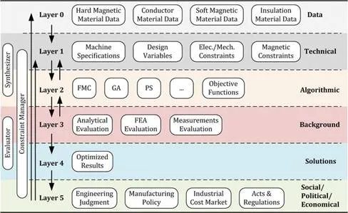
The complex problem of the development of high-power density direct-drive SPMSMs for a light HEV can be solved by using a knowledge-based system (KBS), similar to that analytically described in [31]. The proposed architecture scheme (depicted in Figure 1) involves a number of knowledge sources (KS) and several layers that interact with each other, in order to ensure that the final solution is acceptable from technical, economical and manufacturing point of view. The first two layers (layer 0 and 1) incorporate the provided information about the properties of high quality steels, soft magnetic conductors and insulation materials, while at the same time userís demands, machineís specifications, design variables and problem constraints are also determined. At the next level, the appropriate objective functions, taking into account the aforementioned, are constructed and an optimization method (e.g. genetic algorithm) is applied. At layer 3, an analytical evaluation of all the alternative derived solutions is conducted through FEA and post-processing analysis. Finally, the optimal motor configuration is selected (layer 4) and its application in HEV industry is thoroughly investigated
The above approach was enhanced and finally an overall PMSM design and HEV performance assessment procedure is introduced in order to be a useful tool in the HEV design industrial process. This methodology is based upon the efficient design of the in-wheel motors and the determination of their average driving cycle efficiency. Furthermore, an analytical HEVís model, which has been developed in Matlab/Simulink, incorporates all the necessary subsystems of the vehicle. The internal combustion engine, the two identical SPMSMs coupled in the front wheels, the batteries pack, the dc-dc converter, the three-phase inverter, the power-split device and the control strategy are implemented in this model in order to permit a more realistic study of HEVís behaviour. For instance, the batteries model would make it possible to define the maximum provided voltage dynamically, while the state of their charge, the effect of their internal resistance, the effect of the prevailing temperature and working conditions can also be studied. Thus, a more appropriate selection of each single subsystem can be made resulting to an optimal energy management and performance.
The first step of the proposed methodology, which is presented in flowchart form in Figure 2, is the determination of motorís rated parameters, such as output power, speed and torque. These features are defined based on vehicleís speed and grade-ability along with the collaboration of in-wheel motors with the internal combustion engine. The outer motor diameter is fixed by the size of the wheel and the maximum dc-link voltage is also estimated by the battery pack and converter specifications. For the design of the SPMSMs a combination of classical design theory and meta-heuristic optimization techniques can be applied. The designer can choose among popular techniques based on swarm intelligence, such as genetic algorithm (GA), particle swarm optimization (PSO), ant colony optimization (ACO), etc. In [32], it is outlined that another new method calledďGrey Wolf OptimizerĒ (GWO) exhibits acceptable and satisfactory performance when implemented in similar machine design problems. Based on the results of authorsí previous works (i.e. [20, 21]), where different optimization methods were applied and compared, it was found out that all the adopted algorithms succeeded to converge to a (sub)-optimum design solution. Despite the fact that GA presents higher computational cost and complexity than PSO, fmincon and pattern search, its solutions have been proven the most attractive among others. The same conclusion was validated for all the examined case studies, in which different performance quantities were also of primary concern. Additionally, the main advantages of GA are its capacity of parallelism detection between different agents and its elitist selection. The first characteristic is crucial for the computation of Pareto solutions, whereas the latter one ensures that the best solutions are passed to the next iterative step without major changes. Following these, GA has been finally chosen for the specific optimization problem.
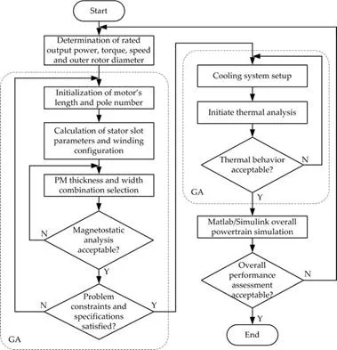
††††††††††† Afterwards, the initialization of motorís length and poles number is following. The first parameter is specified by the size of the tire and the latter should be chosen carefully as it is of great importance for the overall motor performance [33]. The proper poles and slots combination can eliminate the presence of higher order harmonics in the air gap flux distribution, which results in lower iron losses and torque ripple. The motor must be capable of providing high torque when the vehicle accelerates while its losses should be as low as possible. Moreover, concentrated winding configuration is preferable for this traction system, since it presents shorter end windings and higher slot fill factor compared to the corresponding ones of distributed windings, and contributes to a smaller motor volume and lower copper losses, respectively. High power and torque density are very essential characteristics for such an application since there is restricted space inside the wheel. Furthermore, a high efficiency should be achieved over a wide speed range. Thus, the minimization of motorís volume simultaneously with the enhancement of efficiency will be of great concern during the construction of the objective functions. A weighted linear scalarization function is proposedóas a cost functionóin order toďtranslateĒ the original multi-objective problem into a single-objective one which can be solved more easily. This function presents simplicity and thus the overall optimization complexity is reduced. Let the general form be CFj= βi⋅Qi, where βi is a 1 ◊ i row matrix which contains the weight coefficients of the cost function and Qi is an i ◊ 1 column matrix, which contains the values of any motorís quantities under optimization. Numerous cost functions can be produced in this way by altering the weights and/or quantities according to the problem specifications and userís requirements. Normally, a semi-exhaustive search has to be done first in order to explore weights search space for linear scalarization and, consequently, to identify efficient weight combinations. In the case examined here, we consider the motorsí weight (Mtot) and efficiency (η) as equally important quantities for optimization, thus the above cost function is formulated as CF = 0.5 Mtot + 0.5 (1 − η).
Next, the optimization procedure is applied for the determination of numerous variables, such as stator slot configurations, the number of turns per phase, the thickness and the width of permanent magnets, etc. At each step of the proposed approach, a large amount of constraints have to be met. Some of them are imposed in order to ensure the acceptable electromagnetic behaviour of the motor. For example, the motorís rotor yoke should be sufficient enough in order to ensure that no saturation will occur on this part of the machine. Likewise, the maximum acceptable flux density at other parts of the motor will also be set as problem constraints. The estimation of various electromechanical quantities using FEM analysis is indispensable in order to find out if any of these constraints is violated. If this happens, the adopted variables and geometrical parameters of the investigated topology have to be modified and the procedure returns to its initial step.
Another significant constraint is the maximum allowable value of the current density. For a totally enclosed in-wheel motor this value cannot exceed 10 A/mm2 because there is no physical air circulation and temperature alleviation. Thus, the determination of this parameter and motorís thermal behaviour is essential in order to ensure high driving performance even under overload conditions, reduce the risk of magnets demagnetization and enhance the durability of insulation materials. Also, the implementation of a liquid cooling system for the motor is required. The research in recent literature revealed that the commonly used cooling system configurations are not suitable enough for this application. The oil-spray cooling method, which uses a radiator, is very energy consuming and increases the manufacturing complexity and the installation cost [34]. The implementation of ducting system and slot water jackets is difficult due to the limited space [35]. For the same reason, circumferential and axial water jackets are difficult to be applied, since the length of the motor is very short. Consequently, a more appropriate cooling system topology, which is effective enough despite the small cooling system surface, is developed and described thoroughly in the next Section. For each derived motor configuration, its thermal model and the thermal model of the proposed cooling system are constructed, the heat sources and the materials properties are specified, and the boundaries conditions and the temperature coefficients are determined. Finally, the temperature distribution and the overall performance of the cooling system are estimated. Its parameters are calculated by taking into account the optimal energy management of the HEV and the fact that the systemís energy consumption must be kept as low as possible. The aim of the incorporation of motorís thermal analysis in the proposed methodology is to guarantee that motor designs which gather efficient performance and meet the specific problem requirements will not be excluded at this step of the design procedure due to over temperatures and high value of current density.
After applying all the eliminatory criteria, only optimal topologies are selected. Their geometrical parameters and specifications, such as stator phase resistance, inductance in d- and q-axis, flux linkage established by magnets, number of pole pairs, efficiency at rated power, source frequency, shaft inertia and damping coefficient, are then imported in Matlab/Simulink HEV model. This model, as mentioned before, involves all the necessary HEV subsystems and it will be used in order to assess the overall system performance. The final HEV configuration and motor topology will be chosen according to the optimal energy management and efficient collaboration of the subsystems. For this purpose, HEV performance can be estimated during one single or several different driving cycles. The designer should carefully choose the appropriate driving cycle, which fulfil his own requirements and the use of the vehicle. The urban driving cycle (ECE 15) and the New European Driving Cycle (NEDC) have been extensively employed by manufacturers for vehicle energy consumption and emission testing, as they represent the typical use of light duty vehicles in Europe.
Summarizing, the methodology proposed here seems to be very promising compared to other common practices, since it permits the detail implementation of motorís characteristics in HEV model and the interaction between its geometrical parameters with vehicleís performance. Additionally, the user can thoroughly compare to each other several candidate topologies before making his final choice, by examining aspects, such as the fuel consumption, the state of charge of the batteries, the compatibility of inverterís specifications with motorís requirements, etc. The large amount of constraints, the determination of motorís temperature distribution and electromechanical performance can ensure that the in-wheel motor will exhibit the desirable operation even under adverse working conditions. The relatively high simulation time that is required for running Matlab/Simulink model could be considered as the main disadvantage of the proposed here design procedure.
Case studies, results and discussion
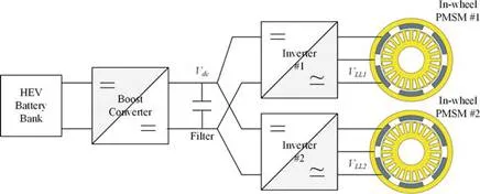
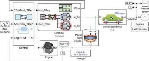
In this Section the problem of the design and optimization of a light duty HEVís traction system is examined. The HEV under consideration incorporates the series-parallel configuration, using an internal combustion engine (ICE) and two SPMSMs for propulsion. The electric motors are implemented around each of the driving wheels to directly deliver power to them. Series-parallel architecture enables the engine and electric motors to provide power independently or in conjunction with one another. At lower vehicleís speeds the system operates more as series vehicle, whereas at high speeds, where the series drive train is less efficient, the engine takes over and energy loss is minimized. The engine is going to be able to produce 115 Nm torque at 4200 rpm, whereas its output power and its maximum speed will be 57 kW and 5000 rpm, respectively. The output power of each in-wheel motor will be equal to 15.3 kW and a torque of 170 Nm at 850 rpm will be provided. Moreover, the engine is going to drive a salient pole synchronous permanent magnet generator, which will either charge the batteries or provide power directly to the electric motors depending on vehicleís mode. A planetary gear is used in order to split power among the engine, the generator and the differential. The nominal voltage of the battery pack is 201.6 V comprising 168 nickel-metal hydride (NiMh) cells, and its nominal capacity is 6.5 Ah. The battery pack voltage is raised by a boost converter leading to a 400 V dc-link voltage. Finally, each in-wheel motor is fed through a three-phase inverter (Figure 3) and is individually controlled using vector control method. For the assessment of the overall system performance, a HEV model, which is available in Matlab/Simulink version R2016a (Figure 4) has been modified properly in order to meet the specific problem requirements. This model permits the study of vehicleís dynamic behaviour, as the aerodynamical and frictional phenomena are included. The vehicleís and its component specifications of the case study are presented in Table 1.

†††††††††††† The design of a high-power density in-wheel motor is a complex optimization problem which will conclude to the most suitable candidates according to some criteria. There are several requirements that have to be met. Some of them are related to the motorís placement and physical constraints, such as its outer rotor radius and active length, whereas others are imposed by the motorís desired operation. The efficiency, for example, is of great importance considering the energy consumption. Efficiency higher than 90% will be an appropriate choice. Despite that, since the motor is mounted inside the wheel, as depicted in Figure 5a, its weight must be as low as possible in order to reduce unsprung mass and eliminate vibrations. Recently in-wheel motors with power-mass ratio of approximately 1 kW/kg have been implemented in commercially available HEVs. In this study, it will be investigated if this value can be exceeded. Thus, the objective function chosen for the case study is a compromise of motorís weight and power losses minimization. The desired SPMSMs characteristics are given in Table 2.

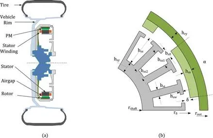
Furthermore, there are more than 15 design variables that have to be optimized simultaneously (under certain constraints) by the applied algorithm. Apart from the geometrical parameters that are presented in Figure 5b, variables such as the number of poles (2p), the number of slots per pole per phase (q) and the number of conductors per slot (nc) are also involved. Table 3 summarizes the upper and lower bounds of all these quantities that will be considered as problem constraints. At this point, it must be mentioned that for sake of space, the analytical equations that describe the electromechanical and magnetic behaviour of the specific machine are not given here. The reader can refer to [18, 36] for more details. Concerning the materials used for different motorís parts, a high quality silicon steel (M19-24G) has been selected both for stator and rotor, according to NEMAís instructions for super premium efficiency motors. Moreover, high energy NdFeB magnets have been chosen, as they have been proven efficient and reliable enough for this kind of application [37]. The values of materials properties will be regarded as constants during optimization problem and they are presented in Table 4.


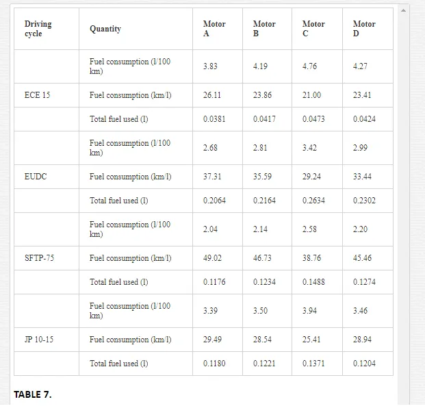
Following the methodology proposed here, a set of optimization results are presented in Table 5, in which the design variables of four final solution topologies are given. Let us denoteďMotor AĒ up to ďMotor DĒ the derived in-wheel configurations. Their electromechanical performance has been validated through 2D and 3D FEM and considered acceptable and satisfactory enough. The obtained results are summarized in Table 6. Moreover, the overall HEVís system behaviour assessment has been conducted by examining vehicleís subsystems collaboration and calculating fuel consumption during four different driving cycles, which are depicted in Figure 6. Among the applied driving cycles are (a) European Driving Cycle ECE 15, (b) Extra Urban Driving Cycle (EUDC), (c) Supplemental Federal Test Procedure (SFTP-75) and (d) Japanese 10-15 mode driving cycle (JP 10-15). During ECE 15 cycle the vehicle covers a distance of 0.9941 km in 195 sec. The average and the maximum vehicleís speed are equal to 25.93 km/h and 50 km/h, respectively and its maximum acceleration is 1.042 m/sec2. EUDC represents a more aggressive and high speed driving mode. The maximum developed and average speeds are equal to 120 km/h and 69.36 km/h, respectively. SFTP-75 is commonly used for emission certification and fuel economy testing for light duty vehicles in United States. This cycle involves both driving in urban areas and high speed road. In this case study, only the second part of this cycle is incorporated. The duration of JP 10-15 is 660 sec and its average speed is 22.7 km/h. A fuel consumption lower than 5.0 l/100 km has been considered acceptable and each topology that did not meet the specific requirement has been excluded from the next step of the proposed methodology. The optimization procedure was terminated when for an investigated configuration the target was achieved for all the examined driving cycles. The relative results are presented in Table 7. From Tables 5Ė7, it is initially clear that the proposed approach succeeded in finding optimum and feasible design solutions satisfying all the existing constraints. Analytically the following can be observed:



I. The optimization procedure provided solutions over the examined range of poles number and the final topologies are investigated and compared to each other from several aspects. The designer has the opportunity to evaluate the derived results from many points of view (i.e. technical, economical, etc.) and finally select the appropriate in-wheel SPMSM topology.
II. The motors efficiency has been found high enough, as it varies from 94 to 95.5%. This feature, especially when is combined with the lowest possible current, is of great importance for HEVís energy management. Concerning this, Motor A seems to be a more suitable choice for the case study.
III. All topologies exhibit high power to mass ratio over 1 kW/kg, since their mass range is from 12.5 to 14.8 kg. In the case of Motor C, the ratio is increased by 22%. Thus, if motorís total mass is the primary objective, this motor prevails. Despite their relatively low weight, all configurations present durability and do not suffer from mechanical stresses.
IV. The volume of NdFeB magnets is small, which will lead to a reasonable motorís cost.
V. The current density constraint has been fulfilled. However, concerning the short axial length of the machine (30 mm) and its placement into a totally enclosed environment the implementation of a cooling system, which has been also proposed and optimized here, is more than essential. More details about the cooling systemís characteristics and its performance are going to be provided later in this chapter.
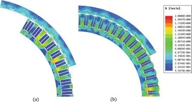
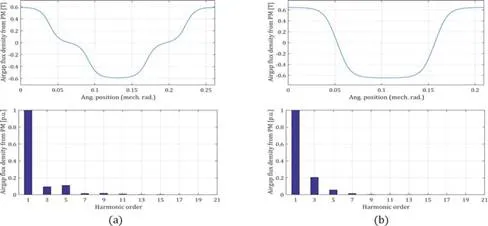
VI. During the adopted design approach, a large amount of motor features were also determined, as they significantly affect its operation. Some of great importance estimated quantities are airgap flux density, torque and phase-back emf curveís shape, as well as their corresponding harmonics, cogging torque, torque angle and magnetic field distribution. For completeness purposes, these quantities are depicted in Figures 7Ė11, indicatively for Motor C and Motor D. As it can be seen from Figure 7, the values of flux density developed over the different parts of both configurations are found within acceptable limits. Despite the low volume and especially active length of the motor, non-saturable operation has been detected for all the finally proposed topologies. Moreover, the airgap flux density and the phase-back emf, as depicted in Figures 8 and 9, respectively, present low harmonic content. The proper selection of windings configurations along with the specification of permanent magnets parameters through the proposed approach contribute to this feature. The airgap flux is of great importance of the torque pulsation. The small amplitude of its third, fifth and seventh harmonic in both cases resulted in the low value of motors torque ripple. The torque ripple for Motor C was found equal to 3.3%, while the same parameter for Motor D was equal to 2.4%. The above can also be validated by the observation of Figure 10, in which the torque and its harmonic content is presented. A very low cogging torque and relatively torque angle is also achieved, as it can be seen from Figure 11. These parameters are essential for this kind of traction application, as their low value can ensure a high quality and safe driving performance.
VII. The calculation of crucial HEVís parameters, such as fuel consumption, permits a better approximation of the optimal configuration. For example, Motor A seems to have a significant advantage compared to the other motors over all examined driving cycles, when the aspect of fuel consumption is examined. This may not be so clear if only the motorís rated performance characteristics were taken into account.

At this point, Motor C, which exhibit the higher nominal current compared to other topologies, is going to be used as a case study for the description of the applied cooling system. It must be outlined that a suitable cooling topology for this kind of motor should gather the following features: (a) be easily implemented in the restricted surface of the motor and (b) be close as much as possible to the part of the machine, which is the main heat source (i.e. stator copper windings). Taking these into account, the attachment of a cooling channel into the inner yoke circumference is proposed. This configuration, which looks like a ring, permits the circulation of a coolant through a pipe with rectangular cross section and the removal of the heat from the inner stator surface. A pump combined with a heat exchanger/compressor for the alleviation of coolantís temperature will consist of the overall cooling system. The accurate position of the cooling channel is shown in Figure 12, in which the shell, the rim and the tire are also presented. All these will be parts of the developed thermal model in order to have a more accurate temperature determination. Moreover, during thermal analysis the temperature and the pressure inside the rim will be taken into account. Compared to other cooling system schemes, the proposed here topology enables a larger contact area between the stator and the coolant, simpler manufacturing and installation procedure and lower cost.
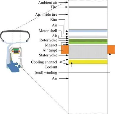
The design procedure of the proposed here cooling system requires the incorporation of an optimization method along with the conduction of motorís thermal analysis through FEM under different operating conditions. The specifications of its parameters, such as the coolantís flow rate and coolantís inlet temperature are of great importance for systemís efficiency and they will be calculated through the applied optimization algorithm. Since these parameters have essential effect on HEVís energy management, their values have to be carefully selected. For example, a high value for coolantís flow rate will conclude to increased energy consumption by the pump in order to circulate the liquid. Likewise, the heat exchanger should be capable of restoring coolantís temperature while its capacity will remain as low as possible. During this procedure, cooling channelís dimensions will be considered as variables. An aluminium alloy (6060-T6) with good mechanical properties has been selected for the channel, while ethylene-glycol mixed with water (50-50 volumetric proportion) has been chosen as coolant. The applied methodology involves the following the steps: (a) the determination of the thermal properties of all involved materials (including the shell, the tire and the insulation materials), (b) the specification of motorís heat resources and the ambient temperature, (c) the calculation of the boundary conditions in the air gap and other motorís parts and (d) the modification of the 2D thermal modelling according to the prevailing conditions. Reader can refer to [38Ė40] in order to find more details about the classical theory governing the thermal analysis and the development of the motorís and cooling systemís thermal model.
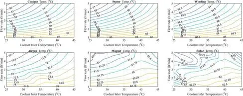
In Figure 13, the influence of coolantís inlet temperature and flow rate in temperature distribution over different in-wheel motor parts is presented. Based on these results and the aforementioned considerations, the inlet temperature of 30oC along with a flow rate of 4 l/min has been chosen as the optimal combination. Moreover, the channelís length, width and breadth have been specified to 30 mm, 10 mm and 1.5 mm, respectively. The derived requirements for heat exchanger, pump and pipe can be easily fulfilled by commercially available models. Figure 14 shows the maximum observed temperatures of motorís parts for the same operating conditions without and with the application of the proposed cooling system. It can be easily observed that a significant temperature drop is achieved with the implementation of the cooling system at all the different loading conditions and the cooling system is considered efficient enough. The maximum heat removal is occurred in stator yoke and the copper windings. The maximum observed temperature in stator slots is far from the insulation materials limits. The temperature developed in air gap and especially near the magnets is relatively low and there is no risk of magnets demagnetization.

Conclusions
In this chapter, the perspective of direct-drive traction systems for HEVs, which lately concentrates on increasing interest among researchers and manufacturers but is not adequately investigated in the literature, is examined. A design and optimization methodology for the development of high-power density in-wheel motors and the corresponding beneficial assessment of the overall HEVís system performance is derived and discussed thoroughly. This approach is enhanced with the incorporation of a simple though efficient cooling system and the interaction of motorís geometrical parameters and performance with the vehicleís subsystems by using a dynamic HEV model. Through a case study, the particular problem requirements and constraints, the eliminatory criteria and the motorís topology selection strategy are illustrated and commented. Based on the overall results, the introduced methodology seems very promising and could be of great aid to designers in order to conclude to the optimal motor configuration.
†††††††††††††††††††††††††††††††††††††††††††††††††††††††††††