Introduction to Performance Analysis of an Integrated Starter-Alternator-Booster for Hybrid Electric Vehicles
As the electrification of vehicle propulsion at low (e-bikes) and high power (buses) continues to extend, the current research efforts on this topic are focused especially on increasing the autonomy of vehicles due to the accumulation of electricity. Due to the lack of charging station and low autonomy in terms of maintaining a reduced weight of the battery, the electrical vehicle is momently limited to urban trails. In this context, the hybrid electric vehicles (HEVs) were considered initially as a transition between conventional vehicles (internal combustion engine (ICE)) and the electric ones, and now they still remain a viable solution that is gaining ground by combining the advantages of both types of vehicles [1–4].
The trend in all types of vehicles (conventional, electrical, or hybrid vehicles) for the next years is to increase the equipment with different types of electrical subsystems. These can be related to the safety (direction, breaking, lights, distance sensors, mirrors etc.) or to the comfort (seats, HAVC, audio, navigation display etc.). At the same time, a lot of traditional mechanically driven loads are replaced with electrical driven ones (water pumps, servo steering, ventilation fan, etc.). This demand of electrical energy, of around 10 kW [5], requires increasing generator power and a certain level of efficiency (normally situated at 40–55%) [6]. A common alternator in a car is relatively cheap and with low efficiency, but with the expected increase of power, it exceeds the capability of the Lundell generator (claw pole synchronous machine). In this context, the replacement of classical alternator with a high efficiency machine is mandatory. Besides this, the operating mode of the conventional starter (around 1 s for each start) is used only for the start of the ICE and after it becomes an extra weight in the vehicle. The easy (costs and implementation) solution of this problem is to replace both machines (starter and alternator) with a single electrical machine.
The initial concept of the integrated starter-alternator (ISA) system was developed in order to gain more space for the powertrain system and to reduce the weight of the vehicle by combining the starter with the alternator. This system ensures the start/stop of the internal combustion engine and the supply with electricity of all the auxiliary subsystems (safety or comfort).
Especially in parallel configuration of HEV, the ISA is used for starting the internal combustion and supply the electrical load. A second electrical machine is necessary for the electric propulsion. The method for the simplification of this structure involves the use of a single electric machine comprising three operating modes: starter-alternator and booster. In this case, the integrated starter-alternator-booster (ISAB) system will be able initially to start the ICE, then, when it is turned on, it will reverse to generator mode and will supply electricity to consumers and the storage system. By adopting adequate control strategies, the electrical machine is capable of moving quickly from generator to motor (booster) and back in order to help the international combustion engine for a short period of time (maximum 2–3 min), if more power is necessary (overruns, ramp, curbs, etc.) [7]. This operating mode of the machine is generically called integrated starter-alternator-booster (ISAB). Using ISAB in parallel HEV is generically called Mild-HEV. In this configuration, the full electric propulsion of the vehicle is not possible, but the production costs necessary for the implementation of the hybridization in conventional vehicles are lowest compared to other variants of HEV.
According to Ref. [8], where the influence of fuel consumption for a small car equipped with ISAB is investigated and considering the European standard (1999/100 EC), the fuel consumption is reduced to about 12% in total.
The increase in the number of electric components within the vehicles boosts the market for electrical motors for hybrid and electric vehicles. A Frost & Sullivan market research finds that the market earned revenues of about 55 million Euros in 2010, which are expected to reach $1.6 billion by the end of 2017 [9].
The required characteristics of the ISAB in the starter mode and alternator (generator) mode are very restrictive for a conventional electrical machine [10]:
· High value of electromagnetic torque for starting ICE (120–300 Nm).
· High efficiency at wide speed range (600–6000 rpm).
· Reliability at high vibrations and over 250,000 start/stop cycles (during 10 years).
· Operation at temperatures between −30 and 130°C.
· Easy maintenance and low cost and so on.
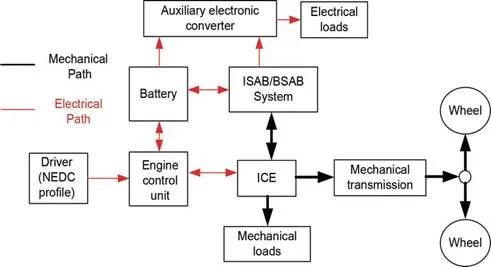
Usually, the ISAB can be connected with a gasoline or diesel engine, either directly through the crankshaft (see Figure 1) or indirectly through the belt system (see Figure 2); based on that, the systems are called belt-driven starter-alternator-booster (BSAB) and conventional ISAB, respectively.
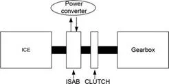
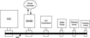
The size of the electrical machine is very important for BSAB application in order to keep the overall size low (the same dimensions like the ones of a conventional alternator) but for a given maximum torque, the systems usually have a recommended gear ratio 3:1 to the ICE crankshaft, according to Ref. [8]. The BSAB runs with a speed three times higher than the ICE. For the ISAB, the speed range is usually synchronized with combustion engine.
Electrical drive used for ISAB applications
ELECTRICAL MACHINES
In the last decade, the development of power electronics (inverter/convertor) made the alternative current (AC) machines the best solution for ISAB applications, especially due to their high power density. These are synchronous reluctance machine (SynRM), induction machine and permanent magnet synchronous machines (PMSM) in both supplying variants: with sinusoidal and trapezoidal current.
The detailed investigation of SRM and induction machine is presented in Refs. [11, 12]. In these studies, the complicated electronics needed for SRM and the difficult control of the induction machine (influence of slip in performance of the machine) are highlighted. In this context, the SynRM and PMSM are the best candidates for ISAB applications.
The electrical machines used for conventional ISAB applications are exposed at high temperatures generated by ICE. This makes impossible the use of the PMSM in high efficiency and low-cost conditions (only with a special method for cooling or using expensive SmCo magnet). Therefore, the SynRM without permanent magnets is the best solution for the direct connection to the crankshaft of ICE (ISAB) and PMSM machine for BSAB.
PMSM MACHINE FOR BSAB APPLICATIONS
The main advantage of the PMSM compared with other types of electrical machine is their high efficiency due to the absence of the field coil losses. The stator is constructed from three-phase windings and steel sheets (the same as the induction machine), but due to the absence of iron losses, the rotor is built from massive steel and permanent magnets. The position of the permanent magnets can be categorized as surface-mounted type and interior type. This position can have a significant effect on the mechanical and electrical characteristics, especially on the synchronous inductance [13]. Because the permeability value of rare earth magnet (such as NdFeB) is very close to that of the air, the air gap of the machine with mounted surface PM effectively becomes larger in this case. This makes the machine d-axis inductance value very low, with a significant effect on the ability of overloading the machine and operation at flux weakening. Because the maximum torque is inverse proportional with the d-inductance, this becomes very large. But the low value of d-inductance reduces the possibility to operate at flux weakening. This is caused by the need to use a high value of the demagnetization component of the stator current in order to decrease the flux value in the air gap. Therefore, the remained current on the q axis will be insufficient to produce torque.
In the case of the interior magnets, it is possible to obtain a sinusoidal distribution of the air-gap flux by using simple rectangular magnets. A sinusoidal flux distribution reduces considerably the cogging torque, in particular in the case of the machine with a large number of pole pairs and a small number of slots per pole and phase [14]. For these structures, it is also possible to increase the flux density in the air gap beyond the value of the remnant flux density of the magnets by using the flux concentrators. Because in this case the d-inductance is usually higher than with that of the surface magnets topologies, the overload capacity of the machine will be reduced and the performance in flux weakening conditions will be higher.
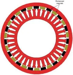
The PMSM with outer rotor (PMSMOR) (see Figure 3) is one of the special topologies of PMSM, with some advantages for BSAB applications:
· Belt mounted directly on the outer rotor, without using pulley.
· Easy mounting of permanent magnets, the centrifugal forces do not influence their mechanical stability.
· High torque capabilities.
· Convenience of cooling, etc.
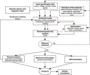
The development cycle of PMSM (inner or outer rotor) topologies includes analytical procedure, magnetic field analysis and optimization procedure connected to previous design steps. The analytical procedure is presented in detail in Refs. [13, 14] and includes the following topics: analysis of the specifications, selection of the topology, the active and passive materials, sizing the machine, choice of the manufacturing technologies and information about preliminary cost evaluation. In the dimensioning procedure, classical formulas or dedicated software platforms like SPEED software can be used.
The electromagnetic flux analysis is realized with dedicated programs (like Flux 2D/3D, Jmag 2D/3D, Maxwell 2D/3D, ANSYS, Opera, open-source programs, etc.) based on the finite element method (FEM). The FEM is a widely used method for obtaining a numerical approximate solution for a given mathematical model of the machine. The obtained results are related to the voltage/current waveform, map of flux density, electromagnetic torque, losses (iron and Joule), and the efficiency value or map of it.
The optimization of electric machine is a multivariable, nonlinear problem with constraints. In order to treat problems with constraints, it is necessary to transform them into unconstrained ones. This can be done, for instance, by embedding the constraints in the objective function. The most used optimization algorithms in design of all types of electrical machines are as follows: genetics algorithms (GA), differential evolution algorithm (DEA), estimation of distribution algorithms (EDAs), particle swarm optimization (PSO) and multi-objective genetic algorithms (MOGA, Pareto, etc.) [15].
A comprehensive evaluation of optimization algorithms was performed in Refs. [16–18]. The authors of these studies state that any such classification of different optimization algorithms is not truly appropriate since the performance is an objective closely related to the specifics of each application. Nevertheless, in the optimization of the electrical machine, the authors mostly agree that DEA achieves the best fitness values, i.e. the minimum objective function value, usually with a smaller number of evaluation steps.
Considering the important step in the development of cycle of PMSM presented above, a general design procedure of PMSMOR for BSAB applications is proposed and presented in Figure 4.
SYNRM MACHINE FOR ISAB
APPLICATIONS
Variable reluctance synchronous machines have received little attention in various comparative studies approaching the selection of the most appropriate electric-propulsion system for either HEV or EV. Malan [19, 20] showed that the SynRM drive has major advantages in electrical propulsion. SynRM’s performance strongly depends on the saliency ratio, but increasing the saliency complicates the rotor construction and drastically increases the motor cost. Interesting results concerning the influence of the saliency ratio on the SynRM steady-state performances, mainly on power factor and efficiency, are given in Ref. [21], while the effect of rotor dimensions on d- and q-axis inductances in the case of a SynRM with flux barrier rotor is discussed in Ref. [22]. Thus, the number of rotor flux barrier for the SynRM recommended in the literature is four. Above this value, the technology of the rotor is too complicated, while for a value lower than 4, the value of the torque ripple is too high. Regarding the rotor construction, there are three main different types, given in Ref. [23], presented in Figure 5
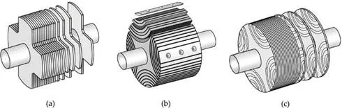
· With salient rotor poles (see Figure 5a): require low technological effort and are obtained by removing the iron material from each rotor pole in the transversal region.
· With axially laminated rotor (ALA) (see Figure 5b): the rotor core is made of axial steel sheets that are insulated from each other using electrically and magnetically insulation (passive material).
· Transversally laminated anisotropic rotor (TLA) (see Figure 5c): the so-called ribs are obtained by punching and then the various rotor segments are connected to each other by these ribs.
The SynRM has a larger torque density compared with that of IM. This comes from the absence of rotor cage and related losses. A different dynamic behaviour is expected from SynRM due to the specific relationships between currents and fluxes. Because SynRM does not have a traditional cage (especially used for starting), it is necessary to use the modern inverter technology. Therefore, most of the literature on SynRM drives has concentrated mainly on the design and control of the machine with the goal of improving control, efficiency and torque production, drive flexibility and cost [24].
The main drawback of SynRM is related to structural behaviour at high speeds (over 10,000 rpm) because the specific geometry of the rotor involves thin layers of steel and large cut-off areas.
Based on advantages and disadvantages of the SynRM and the specific applications of ISAB (rated speed up to 10,000 rpm), SynRM is one of the most suitable candidates for direct connection to crankshaft. The major advantages are high torque, thermal behaviour (absence of permanent magnets and low average value of iron losses), high value of efficiency at entire drive cycle of functioning, vibro-acoustic behaviour (low noise), etc.
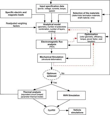
In the development cycle of SynRM presented below, the most important step is related to the rotor geometry and the structural behaviour (see Figure 6).
POWER ELECTRONICS
The electrical equipment installed on the vehicles operates at a nominal voltage of 14 V. In the early 1990s, a new standard (PowerNET) for automotive electrical systems has been proposed by a consortium of automotive manufacturers (Daimler-Benz and General Motors). Following a proposal by the PowerNET, the voltage level increases for the electrical installation to 42 V [25]. The goal was to reduce the section of the conductors and gain the possibility to increase the total power installed in the new generation of vehicle. The standard did not become very popular because of its high implementation costs, which would require the redesign of all electrical and electronical subsystems [26]. Instead, most producers were oriented on systems with two voltage levels: high voltage for propulsion and low voltage for auxiliary and electronic subsystems.
A starter-alternator system involves the use of a static frequency converter for the driving of the electrical machine. The convertor will operate in both the inverter and rectifier regimes. In the rectifier operating mode, it is indicated to adopt a control strategy of the converter with the purpose of reducing losses and the harmonic content of the output currents of the machine. The techniques for the control of the converter for these two modes are the same, only the current reverses its sense depending on the operating mode.
The input voltage of the static frequency converter is a DC voltage, the value of which must be kept constant in order to function optimally. The regulation of the input voltage of the converter can be done by using a bidirectional DC/DC converter with a closed loop control. An alternative to the use a DC/DC stage converter and another DC/AC converter is to use a Z-Source Converter [27]. The Z-Source Converter is more capable compared with the classical converter to operate both as a boost and buck converter due to the input impedances that give it particular operating properties.
POWER ELECTRONICS OF SYNRM AND PMSM
For the control of PMSM machine, the current of the q axis is maintained maximum in order to produce high value of the torque and zero for d axis current, respectively. Instead, for SynRM, the control strategies mean to keep the equal value of the q axis current with the d axis. In the case of PMSM with interior magnets, this control strategy does not provide maximum torque due to the additional reluctant torque [28] component that appears in expression:

Usually, the implemented control method for the PMSM and SynRM for automotive application is an indirect method, which is based on measuring the stator currents and calculating the rotor flux phasor magnitude and position using these currents and the rotor position. Thus, the flux transducer or flux estimators that are usually used in the vector control method with direct measurement of flux are eliminated. This method has a disadvantage due to the fact that the accurate determination of rotor flux phasor position requires a precise measurement of rotor position. Thus, the practical implementation using speed measurement for obtaining the integration of the rotor angle is not recommended. Hence, an incremental encoder position or a resolver, which has a higher cost while providing the precision required of a vector control with a good dynamic response in applications is used. In addition to this vector control method that uses position sensors for determining the rotor angle control, other methods where these transducers are eliminated (sensorless) exist. In these cases, the rotor position is estimated by using complex algorithms, using as input the measurement values of voltages and currents [29].
The general diagram control presented in Figure 7, usually used for PMSM and SynRM, can be divided into power and control components. The power circuit consists of the electrical machine (PMSM/SynRM), DC/DC converter, inverter, while the control loop consists of speed transducer, current transducers, PWM signal generation block, transformation of coordinate systems blocks and computing block of references current.
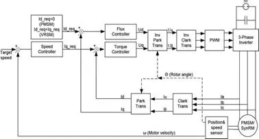
The control strategies considered for the SynRM are:
· Maximum torque control per ampere control (MPTAC)
The model of control is based on imposing the same currents for the d and q axes of the machine as current references for the vector control of the machine. These currents are calculated from the torque equation like


Simulation of a hybrid electric vehicle with the ISAB system
In order to study the electrical machines in ISAB applications, the electric drive model can be introduced and simulated in the Advanced Modelling Environment for performing Simulation (AMESim). AMESim is a multi-domain simulation software for the modelling and analysis of one-dimensional (1D) systems. In this program, each component or physical phenomenon is described by differential equations, type formulation in which the major variable is the time [31]. This approach is different from the partial derivate equations formulation, which formalizes the notion of the distribution of system properties in space. The representation of a dynamic system starting from the notion of “multiport” consists of highlighting the energy exchanges between a component and its environment through the connecting ports. The connection of two or more components through the port allows port exchange power (electrical, mechanical, etc.) according to the adopted sign convention.
For automotive applications, the program comprises discrete components of the ICE, gearbox, control system, electric loads, electrical machine and power inverter, connected together to form a global model of a hybrid electric vehicle.
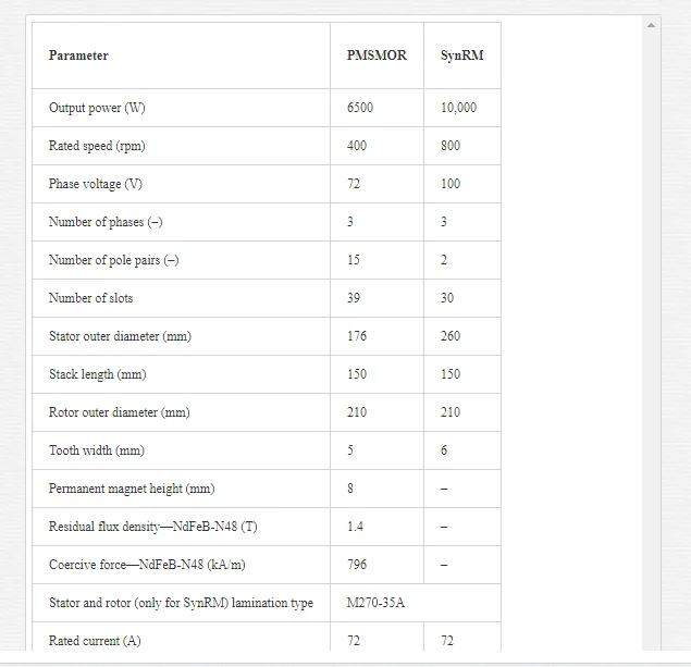
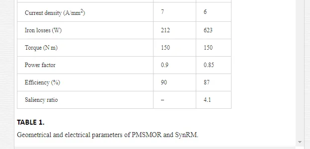
The geometrical and electrical parameters of electrical machine considered for ISAB (SynRM) and BSAB (PMSMOR) application are presented in Table 1. The configuration of PMSMOR is a three-phase machine with 36 slots and 15 poles, and the SynRM topology is a three-phase machine with 27 slots and 4 poles. The dimension of PMSMOR has been imposed according to Ref. [32] (data chosen for belt brushless alternator).
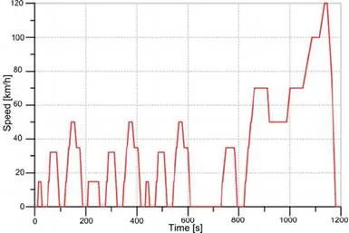
 The simulation of the BSAB and ISAB is carried
out on a New European Driving Cycle (NEDC). A driving cycle is a series of
points defining a speed profile that the studied vehicle must follow [33].
The defined speed profile simulates most common operating modes of an
automobile (frequent acceleration and deceleration, load variations and speed
variations) and corresponds to both urban and extra-urban environments. The
parameters and the profile of NEDC are presented in Table 2 and Figure 8,
respectively.
The simulation of the BSAB and ISAB is carried
out on a New European Driving Cycle (NEDC). A driving cycle is a series of
points defining a speed profile that the studied vehicle must follow [33].
The defined speed profile simulates most common operating modes of an
automobile (frequent acceleration and deceleration, load variations and speed
variations) and corresponds to both urban and extra-urban environments. The
parameters and the profile of NEDC are presented in Table 2 and Figure 8,
respectively.

The model takes into account the most complex thermodynamic phenomena occurring in a heat engine. In the initial implementation, the starter and alternator were a DC permanent magnets machine and the Lundell generator, respectively. The model has been replaced by the studied model and is shown earlier (PMSMOR/SynR). The motors are powered from a battery through the converter DC/DC that will operate in this case as a boost converter.
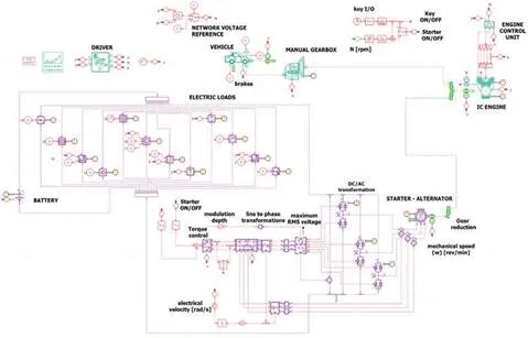
The evaluation of the performance of PMSMOR and SynRM was started from a demonstration model in AMESim of a compact car category (see Figures 9 and 10) with a compression-ignition combustion engine. The imposed weight of the vehicle was 1200 kg (usually between 1134 and 1360 kg, according to Ref. [34]) without any extra weight or passengers.
In order to have comparative results regarding the fuel consumption, in the first simulation, the conventional vehicle functioning during the NEDC cycle was tested. In the next simulations, the ISAB regime with considered electrical machines was established. The behaviour of the starter and alternator in the vehicle model was supposed to be the same as in a conventional car. For the booster regime, a set-up to help ICE for 15 min/h was added and this works in the booster regime only when the battery was fully charged (up to 95%). The time limit for each booster regime was set at 2 min in order to avoid the complete discharging of the battery (but no less than 20%). The parameters of the ICE considered are presented in Table 3.

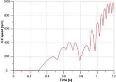
The control of the electrical machines in the starter operating mode involves a maximum torque value (150 N m) until the ICE reaches 350 rpm. Torque command is provided by a bi-positional regulator with hysteresis. It is active when the command of ICE is active and its speed is less than 200 rpm, and it is off when the speed exceeds 400 rpm. When the ICE speed exceeds 300 rpm, the process of fuel injection into the cylinders starts and the ICE accelerates to idle speed. By applying the necessary torque to start the ICE, this is accelerated rapidly at the speed of 400 rpm in about 0.35 s.
When ICE exceeds the speed of 400 rpm, the bi-positional controller becomes inactive and the combustion engine continues to spin out due to its inertia. If the pistons do not reach the maximum compression point, they will not be able to inject fuel to start the combustion process; consequently, the speed drops below 200 rpm and now the controller output is active. Therefore, the starter is controlled again and the combustion engine is brought to a speed of 400 rpm. At the start of the combustion engine process, ICE is accelerated to the idle speed, where it is maintained by the electronic control unit. The entire process of starting the engine (in normal condition), from the beginning until stable operation at idle speed, lasts 0.8 s. In the winter, this process may take 1.5 s. The speed profile of starting the ICE is presented in Figure 11.
For the alternator mode, the nominal value of the electrical loads is considered in the model. Some electrical loads are intermittently connected (fan, electrical window, heating systems, etc.). Other loads are dependent on ICE speed (fuel pump and injectors) or the speed of the vehicle.
When the entire driving cycle is considered, the fuel consumption in the vehicle is reduced to 878.63 ml for the BSAB system and 941 ml for the ISAB system. These values represent a fuel economy of around 16% for BSAB and 17.3% for ISAB of total consumption compared with a classical vehicle with a dedicated alternator and starter (without booster option) system. The difference in fuel consumption is due to the value of nominal power of electrical machines (see Table 1). But, the performances of SynRM are limited by the battery (which uses 75 Ah) capacities. If it uses a stronger battery, the total fuel economy can be increased with 2 or 4% (especially due to the booster mode).
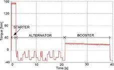
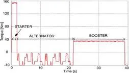
In the mechanical evaluation of electrical machines for automotive applications, the variation of electromagnetic torque is one of the most important parameters, because this variation (torque ripple) can become a source of noise and vibration in vehicles. Thus, for a better visualization of the torque profile of PMSMOR and SynRM, a new scenario for all three regimes was considered. For better comparative results (variation of axis torque) between IASB and BSAB, the BSAB system is taken into account through directly coupling (using ratio 1:1 between ICE and BSAB speed) at ICE. The starter and generator regime has been set for 1.5 and 20 s, respectively. The variation of the axis torque in the generator mode has been obtained by intermittent connection of the electrical loads (lights, HVAC, media, etc.). For the booster mode, the speed of the vehicle is increased from 70 to 120 km/h in 17 s, necessary to overtake other vehicles. In this case, the battery is considered fully charged.
Figures 12 and 13 show the variation of the axis torque versus time for all operating modes, respectively. Due to the proper windings-slot combination, the torque ripple values are below 10%. In fact, the ratio of the torque ripple is 7.1% for PMSMOR and 6.2% for SynRM. In the booster mode, the rated torque value of the 10 kW SynRM machine used for ISAB is obviously bigger than that of the 6.5 kW PMSMOR.
Conclusions
The chapter presents the main steps to be followed in the development of a specific electric drive system dedicated to automotive domain, such as integrated starter-alternator-booster applications. Replacing the starter and alternator in a conventional vehicle with extended possibility to work in booster mode represents the first step of vehicles’ hybridization, called Mild-HEV. In this way, two variants in mounting the ISAB had been identified in the literature: one, directly driven generic called ISAB and another belt-driven called BSAB. In this chapter, the approach contains the major elements that need to be discussed for two type of electrical machine (PMSMOR and SynRM) suitable for BSAB and ISAB, respectively. The general design procedure is presented for these two electrical machines by taking into account the typical constraints of the applications and the behaviour of the machine (thermal, structural, and noise, vibrations and harshness particularities). Also, the control aspects of both electrical machines are presented.
In order to demonstrate the capability of this vehicle hybridization method, two electrical machines have been designed and the equations model was developed and implemented in the general 1D model of conventional vehicle performed in AMESim software. The influence of fuel consumption on the entire drive cycling (NEDC) was investigated. Based on the obtained results, the ISAB system gives a greater value of the reduction of fuel consumption, but the coupling of the electrical machine directly to the crankshaft involves complicated manufacturing techniques (higher cost) compared with the BSAB system procedure.