Gear Introduction
A gear also known as "gear wheel" is a rotating machine part having cut teeth, or cogs, which mesh with another toothed part in order to transmit torque. Two or more gears working in tandem are called a transmission and can produce a mechanical advantage through a gear ratio and thus may be considered a simple machine. Geared devices can change the speed, magnitude, and direction of a power source. The most common situation is for a gear to mesh with another gear, however a gear can also mesh a non-rotating toothed part, called a rack, thereby producing translation instead of rotation.
The gears in a transmission are analogous to the wheels in a pulley. An advantage of gears is that the teeth of a gear prevent slipping.
When two gears of unequal number of teeth are combined a mechanical advantage is produced, with both the rotational speeds and the torques of the two gears differing in a simple relationship.
There are tiny gears for devices like wrist watches and there are large gears that some of you might have noticed in the movie Titanic. Gears form vital elements of mechanisms in many machines such as vehicles, metal tooling machine tools, rolling mills, hoisting and transmitting machinery, marine engines, and the like. Toothed gears are used to change the speed, power, and direction between an input and output shaft.
1) Gears are the most common source used for power transmission.
2) They can be applied for two shafts which are-
· Parallel
· Collinear
· Perpendicular & Intersecting
· Perpendicular and Non-intersecting
· Inclined at an arbitrary angle
Gear Parameters
1) Number of teeth
2) Form of teeth
3) Size of teeth
4) Face width of teeth
5) Style and dimension of gear blank
6) Design of the hub of the gear
7) Degree of precision required
8) Means of attaching the gear to the shaft
9) Means of locating the gear axially to the shaft
Types of Gears
1. Spur Gear
2. Helical Gear
3. Herringbone Gear
4. Bevel Gear
5. Worm Gear
6. Rack and Pinion
7. Internal and External Gear
8. Face Gear
9. Sprockets
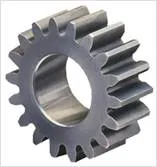
1) Spur Gear-Parallel and coplanar shafts connected by gears are called spur gears. The arrangement is called spur gearing.
Spur gears have straight teeth and are parallel to the axis of the wheel. Spur gears are the most common type of gears. The advantages of spur gears are their simplicity in design, economy of manufacture and maintenance, and absence of end thrust. They impose only radial loads on the bearings.
Spur gears are known as slow speed gears. If noise is not a serious design problem, spur gears can be used at almost any speed.
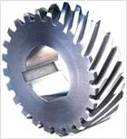
2) Helical Gear-Helical gears have their teeth inclined to the axis of the shafts in the form of a helix, hence the name helical gears.
These gears are usually thought of as high speed gears. Helical gears can take higher loads than similarly sized spur gears. The motion of helical gears is smoother and quieter than the motion of spur gears.
Single helical gears impose both radial loads and thrust loads on their bearings and so require the use of thrust bearings. The angle of the helix on both the gear and the must be same in magnitude but opposite in direction, i.e., a right hand pinion meshes with a left hand gear.
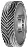
3) Herringbone Gear - Herringbone gears resemble two helical gears that have been placed side by side. They are often referred to as "double helical". In the double helical gears arrangement, the thrusts are counter-balanced. In such double helical gears there is no thrust loading on the bearings.
4) Bevel/Miter Gear-Intersecting but coplanar shafts connected by gears are called bevel gears. This arrangement is known as bevel gearing. Straight bevel gears can be used on shafts at any angle, but right angle is the most common. Bevel Gears have conical blanks. The teeth of straight bevel gears are tapered in both thickness and tooth height.
Spiral Bevel gears: In these Spiral Bevel gears, the teeth are oblique. Spiral Bevel gears are quieter and can take up more load as compared to straight bevel gears.
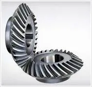
Zero Bevel gear: Zero Bevel gears are similar to straight bevel gears, but their teeth are curved lengthwise. These curved teeth of zero bevel gears are arranged in a manner that the effective spiral angle is zero.

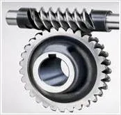
5) Worm Gear- Worm gears are used to transmit power at 90° and where high reductions are required. The axes of worm gears shafts cross in space. The shafts of worm gears lie in parallel planes and may be skewed at any angle between zero and a right angle. In worm gears, one gear has screw threads. Due to this, worm gears are quiet, vibration free and give a smooth output. Worm gears and worm gear shafts are almost invariably at right angles.
6) Rack and Pinion- A rack is a toothed bar or rod that can be thought of as a sector gear with an infinitely large radius of curvature. Torque can be converted to linear force by meshing a rack with a pinion: the pinion turns; the rack moves in a straight line. Such a mechanism is used in automobiles to convert the rotation of the steering wheel into the left-to-right motion of the tie rod(s). Racks also feature in the theory of gear geometry, where, for instance, the tooth shape of an interchangeable set of gears may be specified for the rack (infinite radius), and the tooth shapes for gears of particular actual radii then derived from that. The rack and pinion gear type is employed in a rack railway.

7) Internal & External Gear- An external gear is one with the teeth formed on the outer surface of a cylinder or cone. Conversely, an internal gear is one with the teeth formed on the inner surface of a cylinder or cone. For bevel gears, an internal gear is one with the pitch angle exceeding 90 degrees. Internal gears do not cause direction reversal.
8) Face Gears- Face gears transmit power at (usually) right angles in a circular motion. Face gears are not very common in industrial application.

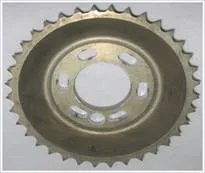
9) Sprockets-Sprockets are used to run chains or belts. They are typically used in conveyor systems.
Gears may also be classified according to the position of axis of shaft:
a. Parallel
1. Spur Gear
2. Helical Gear
3. Rack and Pinion
b. Intersecting
Bevel Gear
c. Non-intersecting and Non-parallel
Worm and worm gears