Hydraulic System of an Automatic Transmission
The hydraulic system of an automatic transmission serves four basic purposes:
1. Actuates clutches and brake bands by hydraulic pressure from the hydraulic slave circuits.
2. Controls the shifting pattern of the transmission. This is done by switching hydraulic pressure to programmed combinations of clutches and brake bands based on vehicle speed and engine load.
3. Circulates the transmission fluid through a remote cooler to remove excess heat that is generated in the transmission and torque converter.
4. Provides a constant fresh supply of oil to all critical wearing surfaces of the transmission.
The hydraulic system for an automatic transmission typically consists of a pump, pressure regulator, manual valve, vacuum modulator valve, governor valve, shift valves, kick down valve, and a valve body.
Pump
The typical hydraulic pump is an internal-external rotor or gear-type pump. Located in the front of the transmission case, it is keyed to the torque converter hub so that it is driven by the engine. As the torque converter spins the oil pump, transmission fluid is drawn into the pump from the transmission pan. The pump compresses the oil and forces it to the pressure regulator. The pump has several basic functions:
• Produces pressure to operate the clutches, the bands, and the gearsets.
• Lubricates the moving parts in the transmission.
• Keeps the torque converter filled with transmission fluid for proper operation.
• Circulates transmission fluid through the transmission and cooling tank (radiator) to transfer heat.
• Operates hydraulic valves in the transmission
Pressure Regulator
The pressure regulator limits the maximum amount of oil pressure developed by the oil pump. It is a spring-loaded valve that routes excess pump pressure out of the hydraulic system, assuring proper transmission operation.
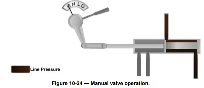
Manual Valve
A manual valve located in the valve body is operated by the driver through the shift linkage (Figure 10-24). This valve allows the operator to select park, neutral, reverse, or different drive ranges. When the shift lever is moved, the shift linkage moves the manual valve. As a result, the valve routes hydraulic fluid throughout the transmission to the correct places. When the operator selects overdrive, drive, or second, the transmission takes over, shifting automatically to meet driver conditions. When the selector is placed in low and reverse, the transmission is locked into the selected gear.
Vacuum Modulator Valve
The vacuum modulator valve is a diaphragm device that uses engine manifold vacuum to indicate engine load to the shift valve (Figure 10-25). As engine vacuum (load) rises and falls, it moves the diaphragm inside the modulator. This in turn moves the rod and hydraulic valve to change throttle control pressure in the transmission. In this way, the vacuum modulator can match transmission shift points to engine loads.

Governor Valve
The governor valve senses engine speed (transmission output shaft speed) to help control gear shifting (Figure 10-26). The vacuum modulator and governor work together to determine the shift points. The governor gear is meshed with a gear on the transmission output shaft. Whenever the vehicle and output shaft are moving, the centrifugal weights rotate. When the output shaft and weights are spinning slowly, the weights are held in by the governor springs, causing low-pressure output, and the transmission remains in low gear. As the engine speeds increases, the weights are thrown out further and governor pressure increases, moving the shift valve and causing the transmission to shift into higher gear.

Shift Valves
The shift valves are simple balance type spool valves that select between low and high gear when the manual valve is in drive. Using control pressure (oil pressure from the regulator, governor, vacuum modulator, and manual valves), they operate the bands, servos, and gearsets. Oil pressure from the other transmission valves acts on each end of the shift valve. In this way, the shift valve is sensitive to engine load (vacuum modulator valve oil pressure), engine speed (governor valve oil pressure), and gearshift position (manual valve oil pressure). These valves move according to the forces and keep the transmission shifted into the correct gear ratio for the driving conditions.
Kickdown Valve
The kickdown valve causes the transmission to shift into a lower gear during fast acceleration. A rod or cable links the carburetor or fuel injection throttle body to a lever on the transmission. When the operator depresses the throttle, the lever moves the kickdown valve. This action causes hydraulic pressure to override normal shift control pressure and the transmission downshifts.
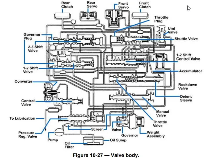
Valve Body
The valve body is a very complicated hydraulic system (Figure 10-27). It contains hydraulic valves used in an automatic transmission, such as the pressure regulator, shift valves, and manual valves. The valve body bolts to the bottom of the transmission case and is housed in the transmission pan. A filter or screen is attached to the bottom of the valve body. Passages in the valve body route fluid from the pump to the valves and then into the transmission case. Passages in the transmission case carry fluid to other hydraulic components.