Transmission Overhaul
Because of the variations in construction of transmissions, always refer to the manufacturer’s service manual for proper procedures in the removal, disassembly, repair, assembly, and installation. The time to carry out these operations varies from 6 to 8 hours, depending on transmission type and vehicle manufacturer.
The basic removal procedures are as follows:
1. Unscrew the transmission drain plug and drain the oil.
2. Remove the drive shaft and install a plastic cap over the end of the transmission shaft.
3. Disconnect the transmission linkage at the transmission.
4. Unbolt and remove the speedometer cable from the extension housing.
5. Remove all electrical wires leading to switches on the transmission.
6. Remove any cross members or supports.
7. Support the transmission and engine with jacks. Operate the jack on the engine to take the weight off the transmission.
Be careful not to crush the oil pan.
Never let the engine hang suspended by only the front motor mounts.
8. Depending upon what is recommended by the service manual, either remove the transmission-to-clutch cover bolts or the bolts going into the engine from the clutch cover.
9. Slide the transmission straight back, holding it in alignment with the engine. You may have to wiggle the transmission slightly to free it from the engine.
Once the transmission has been removed from the engine, clean the outside and place it on your workbench. Teardown procedures will vary from one transmission to another. Always consult the service manual for the type of transmission you are working on. If improper disassembly methods are used, major part damage could possibly result.
Before disassembly, remove the inspection cover. This will allow you to observe transmission action. Shift the transmission into each gear, and at the same time rotate the input shaft while inspecting the conditions of the gears and synchronizers.
The basic disassembly procedures are as follows:
1. Unbolt and remove the rear extension housing. It may be necessary to tap the housing off with a soft face mallet or bronze hammer.
2. Unbolt and remove the front extension housing and any snap rings.
3. Carefully pry the input shaft and gear forward far enough to free the main shaft.
4. Using a brass drift pin, push the reverse idler shaft and countershaft out of the transmission case.
5. Remove the input shaft and output shaft assemblies. Slide the output shaft and gears out of the back of the transmission as a unit. Be careful not to damage any of the gears.
After the transmission is disassembled, clean all the parts thoroughly and individually. Clean all the parts of hardened oil, lacquer deposits, and dirt. Pay particular attention to the small holes in the gears and to the shifter ball bores in the shifter shaft housing. Remove all gasket material using a putty knife or other suitable tool. Ensure that the metal surfaces are not gouged or scratched. Also, clean the transmission bearings and blow-dry them using low-pressure compressed air.
Power Flow
Now that you understand the basic parts and construction of a manual transmission, we will cover the flow of power through a five-speed synchromesh transmission (Figure 10- 14). In this example neither first gear nor reverse gear are synchronized.
Reverse Gear
In passing from neutral to reverse, the reverse idler gear has been moved rearward, and power from the countershaft gear flows into the reverse idler gear. The reverse idler gear directs power to the gear on the outside of the first and second synchronizer. Since the outer sleeve of the first and second gear synchronizer has been moved to the center position, power will not flow through first or second gear. The output shaft and synchronizer remain locked together; rotation is reversed to the countershaft gear and is reversed again on its way through the reverse idler gear. Since the power flow has changed three times, an odd number, direction of transmission spin is opposite of that of the engine (Figure 10-14). The sole function of this gear is to make the main shaft rotate in the opposite direction to the input shaft; it does not affect gear ratio.
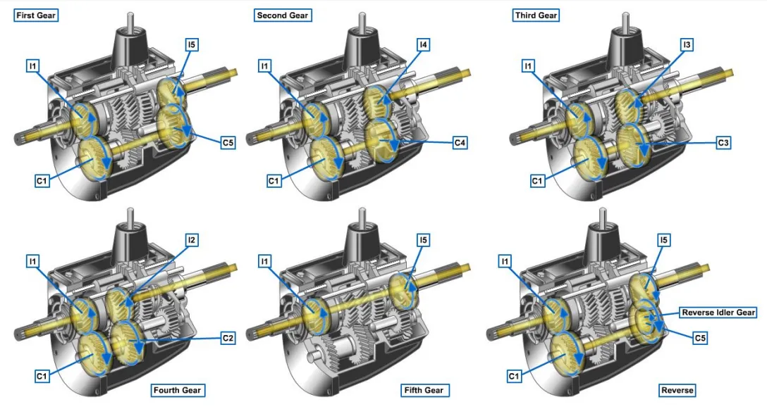
reversed again on its way through the reverse idler gear. Since the power flow has changed three times, an odd number, direction of transmission spin is opposite of that of the engine (Figure 10-14). The sole function of this gear is to make the main shaft rotate in the opposite direction to the input shaft; it does not affect gear ratio.
First Gear
To get the vehicle moving from a standstill, the operator moves the gearshift lever into first. The input shaft’s main drive gear turns the countershaft gear in a reverse direction. The countershaft gear turns the low gear in the same direction as the input shaft. Since the outer sleeve on the first-second gear synchronizer has been moved rearward, the low gear is locked to the output shaft (Figure 10-14). The difference in countershaft gear and first gear results in a gear ratio approximately 3.5:1.
Second Gear
In second gear, the input shaft’s main drive gear turns the countershaft gear in a reverse direction. The countershaft gear turns the second gear on the output shaft to reverse the direction again. This action will result in the rotation of the output shaft to turn in the same direction as the input shaft. Since the outer sleeve on the first-second gear synchronizer has been moved forward, the second gear is locked to the output shaft (Figure 10-14). Gear ratio is approximately 2.5:1.
Third Gear
In third gear, the input shaft’s main drive gear turns the countershaft gear in a reverse direction. The countershaft gear turns the third gear on the output shaft to reverse the direction again. This action will result in the rotation of the output shaft to turn in the same direction as the input shaft. Since the outer sleeve on the third-fourth gear synchronizer has been moved rearward, the third gear is locked to the output shaft (Figure 10-14). Gear ratio is approximately 1.5:1.
Fourth Gear
In fourth gear, the synchronizer outer sleeve moves forward to engage the main drive gear. This will lock the input and output shafts together (Figure 10-14). This is direct drive and gives you a 1:1 gear ratio.
Fifth Gear
In fifth gear, the input shaft’s main drive gear turns the countershaft gear in a reverse direction. The fifth gear synchronizer outer sleeve moves forward. This engages the fifth gear with the counter gear. Since fifth gear is already in mesh with a gear on the output shaft, the synchronizer has locked the counter gear to the output shaft (Figure 10-14). Gear ratio is approximately .7:1.