Clutch Construction
The clutch is the first drive train component powered by the engine crankshaft. The clutch lets the driver control power flow between the engine and the transmission or transaxle. Before understanding the operation of a clutch, you must first become familiar with the parts and their functions. This information is very useful when learning to diagnose and repair the clutch assembly.
Clutch Release Mechanism
A clutch release mechanism allows the operator to operate the clutch. Generally, it consists of the clutch pedal assembly, a mechanical linkage, cable, or hydraulic circuit, and the clutch fork. Some manufacturers include the release bearing as part of the clutch release mechanism.
Linkage
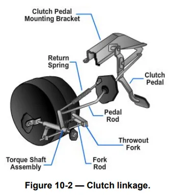
A clutch linkage mechanism uses levers and rods to transfer motion from the clutch pedal to the clutch fork. One configuration is shown in Figure 10-2. When the pedal is pressed, a pushrod shoves on the bell crank and the bell crank reverses the forward movement of the clutch pedal. The other end of the bell crank is connected to the release rod. The release rod transfers bell crank movement to the clutch fork. It also provides a method of adjustment for the clutch.
Cable
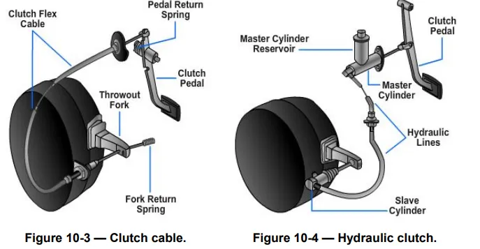
The clutch cable mechanism uses a steel cable inside a flexible housing to transfer pedal movement to the clutch fork. As shown in Figure 10-3, the cable is usually fastened to the upper end of the clutch pedal, with the other end of the cable connecting to the clutch fork. The cable housing is mounted in a stationary position. This allows the cable to slide inside the housing whenever the clutch pedal is moved. One end of the clutch cable housing has a threaded sleeve for clutch adjustment.
Hydraulic
A hydraulic clutch release mechanism uses a simple hydraulic circuit to transfer clutch pedal action to the clutch fork (Figure 10-4). It has three basic parts—master cylinder, hydraulic lines, and a slave cylinder. Movement of the clutch pedal creates hydraulic pressure in the master cylinder, which actuates the slave cylinder. The slave cylinder then moves the clutch fork.
Slave Cylinder with Clutch Master Cylinder
The master cylinder is the controlling cylinder that develops the hydraulic pressure. The slave cylinder is the operating cylinder that is actuated by the pressure created by the master cylinder.
Clutch Fork
The clutch fork, also called a clutch arm or release arm, transfers motion from the release mechanism to the release bearing and pressure plate. The clutch fork sticks through a square hole in the bell housing and mounts on a pivot. When the clutch fork is moved by the release mechanism, it pries on the release bearing to disengage the clutch. A rubber boot fits over the clutch fork. This boot is designed to keep road dirt, rocks, oil, water, and other debris from entering the clutch housing.
Clutch Housing
The clutch housing is also called the bell housing. It bolts to the rear of the engine, enclosing the clutch assembly, with the manual transmission bolted to the back of the housing. The lower front of the housing has a metal cover that can be removed for flywheel ring gear inspection or when the engine must be separated from the clutch assembly. A hole is provided in the side of the housing for the clutch fork. It can be made of aluminum, magnesium, or cast iron.
Release Bearing
The release bearing, also called the throw-out bearing, is a ball bearing and collar assembly. It reduces friction between the pressure plate levers and the release fork. The release bearing is a sealed unit pack with a lubricant. It slides on a hub sleeve extending out from the front of the manual transmission or transaxle and is moved by either hydraulic or manual pressure.
Hydraulic Type
The hydraulic release bearing eliminates the stock mechanical release bearing linkage and slave cylinder. The release bearing mounts on the transmission face or slips over the input shaft of the transmission. When the clutch pedal is pressed, the bearing face presses against the pressure plate to disengage the clutch.
Manual Type
The release bearing snaps over the end of the clutch fork. Small spring clips hold the bearing on the fork. Then fork movement in either direction slides the release bearing along the transmission hub sleeve.
Pressure Plate
The pressure plate is a spring-loaded device that can either engage or disengage the clutch disc and the flywheel. It bolts to the flywheel. The clutch disc fits between the flywheel and the pressure plate. There are two types of pressure plates—the coil spring type and the diaphragm type.