Steering Mechanisms
The fundamental problem in steering is to enable the vehicle to traverse an arc such that all four wheels travel about the identical center point. In the days of horse-drawn carriages, this was accomplished with the fifth-wheel system depicted in Fig.
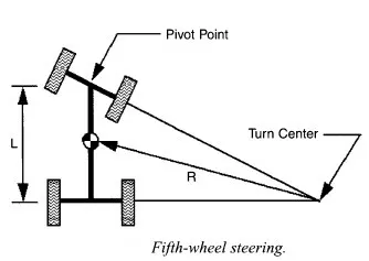
Although this system worked well for carriages, it soon proved unsuitable for automobiles. In addition to the high forces required of the driver to rotate the entire front axle, the system proved unstable, especially as vehicle speeds increased. The solution to this problem was developed by a German engineer named Lankensperger in 18 17. Lankensperger had an inherent distrust of the German government, so he hired an agent in England to patent his idea. His chosen agent was a lawyer named Rudolph Ackerman. The lawyer secured the patent, but the system became known as the Ackerman system.

Figure depicts the key features of this system. The end of each axle has a spindle that pivots around a kingpin. The linkages connecting the spindles form a trapezoid, with the base of the trapezoid formed by the rack and tie rods. The distance between the tie rod ends is less than the distance between the kingpins. The wheels are parallel to each other when they are in the straight-ahead position. However, when the wheels are turned, the inner wheel turns through a greater angle than the outer wheel. Figure 7.2 also shows that the layout is governed by the ratio of track (distance between the wheels) to wheelbase (distance between front and rear wheels). The Ackerman layout is accurate only in three positions: straight ahead, and at one position in each direction. The slight errors present in other positions are compensated for by the deflection of the pneumatic tires.
For the purposes of this book, "steering mechanism" refers to those components required to realize the Ackerman system. Of course, all vehicles today use a steering wheel as the interface between the system and driver. (This has not always been the case. Early automobiles used a tiller.) The steering wheel rotates a column, and this column is the input to the steering mechanism. These mechanisms can be broadly grouped into two categories:
(I) worm-type mechanisms, and (2) rack and pinion mechanisms.
Worm Systems
The steering linkages required by worm gear steering systems. The Pitman arm converts the rotational motion of the steering box output into side-to-side motion of the center link. The center link is tied to the steering arms by the tie rods, and the side-to-side motion causes the spindles to pivot around their respective steering axes (kingpins). To achieve Ackerman steering, the four-bar linkages must form a trapezoid instead of a parallelogram. Although all worm-type steering systems use linkages similar to these, the specifics of the steering boxes differ and are explained next.

Worm and Sector
The shaft to the Pitman arm is connected to a gear that meshes with a worm gear on the steering column. Because the Pitrnan shaft gear needs to rotate through only approximately 70°, only a sector of the gear is actually used. The worm gear is assembled on tapered roller bearings to absorb some thrust load, and an adjusting nut is provided to regulate the amount of end-play in the worm.

Worm and Roller
The worm and roller system is very similar to the worm and sector system. In this case, a roller is supported by ball bearings within the sector on the Pitman shaft. The bearings reduce sliding friction between the worm and sector. The worm also can be shaped similarly to an hourglass, that is, tapered from each end to the center. This provides better contact between the worm and the roller, as well as a variable steering ratio. When the wheels are at the center (straight-ahead) position, the steering reduction ratio is high to provide better control. As the wheels are turned farther off-center, the ratio lowers. This gives better maneuverability during low-speed maneuvers such as parking.

Recirculating Ball
The recirculating ball system, another form of worm and nut system. In this system, a nut is meshed onto the worm gear by means of a continuous row of ball bearings. As the worm turns, the nut moves up and down the worm threads. The ball bearings not only reduce the friction between the worm and nut, but they greatly reduce the wear because the balls continually recirculate through the system, thereby preventing any one area from bearing the brunt of the wear. The primary advantage of all worm-type steering systems is reduced steering effort on the part of the driver. However, due to the worm gear, the driver receives no feedback from the wheels. For these reasons, worm-type steering systems are found primarily on large vehicles such as luxury cars, sport utility vehicles, pickup trucks, and commercial vehicles.

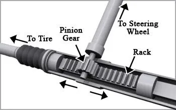
Rack and Pinion Steering
The rack and pinion steering system is simpler, lighter, and generally cheaper than worm-type systems (Fig. 7.7). The steering column rotates a pinion gear that is meshed to a rack. The rack converts the rotary motion directly to side-to-side motion and is connected to the tie rods. The tie rods cause the wheels to pivot about the kingpins, thus turning the front wheels.
Rack and pinion systems have the advantage of providing feedback to the driver. Furthermore, rack and pinion systems tend to be more responsive to driver input, and for this reason, rack and pinion steering is found on most small and sports cars.