The translational or rotational displacement of the follower is a function of the rotary angle of the cam. A designer can define the function according to the specific requirements in the design. The motion requirements, listed below, are commonly used in cam profile design.
Disk Cam with Knife-Edge Translating Follower
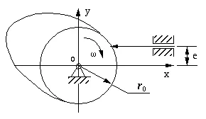
Figure 6-12 is a skeleton diagram of a disk cam with a knife-edge translating follower. We assume that the cam mechanism will be used to realize the displacement relationship between the rotation of the cam and the translation of the follower.
Figure 6-12 A Skeleton Diagram of disk cam with knife-edge translation
Below is a list of the essential parameters for the evaluation of these types of cam mechanisms. However, these parameters are adequate only to define a knife-edge follower and a translating follower cam mechanism.
Parameters:
ro: The radius of the base circle;
e: The offset of the follower from the rotary center of the cam. Notice: it could be negative.
s: The displacement of the follower which is a function of the rotary angle of the cam -- ![]() .
.
IW: A parameter whose absolute value is 1. It represents the turning direction of the cam. When the cam turns clockwise: IW=+1, otherwise: IW=-1.
The method termed inversion is commonly used in cam profile design. For example, in a disk cam with translating follower mechanism, the follower translates when the cam turns. This means that the relative motion between them is a combination of a relative turning motion and a relative translating motion. Without changing this feature of their relative motion, imagine that the cam remains fixed. Now the follower performs both the relative turning and translating motions. We have inverted the mechanism.
Furthermore, imagine that the knife-edge of the follower moves along the fixed cam profile in the inverted mechanism. In other words, the knife edge of the follower draws the profile of the cam. Thus, the problem of designing the cam profile becomes a problem of calculating the trace of the knife edge of the follower whose motion is the combination of the relative turning and the relative translating.
Design equations:

Figure 6-13 Profile design of translating cam follower
In Figure 6-13, only part of the cam profile AK is displayed. Assume the cam turns clockwise. At the beginning of motion, the knife edge of the follower contacts the point of intersection A of the base circle and the cam profile. The coordinates of A are (So, e), and So can be calculated from equation 
Suppose the displacement of the follower is S when the angular displacement of the cam is ![]() . At this moment, the coordinates of the knife edge of the follower should be (So + S, e).
. At this moment, the coordinates of the knife edge of the follower should be (So + S, e).
To get the corresponding position of the knife edge of the follower in the inverted mechanism, turn the follower around the center of the cam in the reverse direction through an angle of ![]() . The knife edge will be inverted to point K, which corresponds to the point on the cam profile in the inverted mechanism. Therefore, the coordinates of point K can be calculated with the following equation:
. The knife edge will be inverted to point K, which corresponds to the point on the cam profile in the inverted mechanism. Therefore, the coordinates of point K can be calculated with the following equation:

(6-5)
Note:
6.5.2 Disk Cam with Oscillating Knife-Edge Follower
Suppose the cam mechanism will be used to make the knife edge oscillate. We need to compute the coordinates of the cam profile that results in the required motion of the follower.
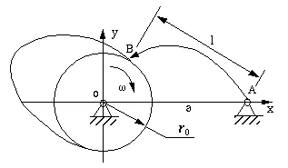
Figure 6-14 Disk cam with knife-edge oscillating follower
The essential parameters in this kind of cam mechanisms are given below.
ro: The radius of the base circle;
a: The distance between the pivot of the cam and the pivot of the follower.
l: The length of the follower which is a distance from its pivot to its knife edge.
![]() : The angular displacement of the follower which is a function of the rotary angle of the cam --
: The angular displacement of the follower which is a function of the rotary angle of the cam -- ![]() .
.
IP: A parameter whose absolute value is 1. It represents the location of the follower. When the follower is located above the x axis: IP=+1, otherwise: IP=-1.
IW: A parameter whose absolute value is 1. It represents the turning direction of the cam. When the cam turns clockwise: IW=+1, otherwise: IW=-1.
Cam profile design principle
The fundamental principle in designing the cam profiles is still inversion, similar to that that for designing other cam mechanisms, (e.g., the translating follower cam mechanism). Normally, the follower oscillates when the cam turns. This means that the relative motion between them is a combination of a relative turning motion and a relative oscillating motion. Without changing this feature of their relative motion, let the cam remain fixed and the follower performs both the relative turning motion and oscillating motion. By imagining in this way, we have actually inverted the mechanism.

Figure 6-15 Cam profile design for a rotating follower
In Figure 6-15, only part of the cam profile BK is shown. We assume that the cam turns clockwise.
At the beginning of motion, the knife edge of the follower contacts the point of intersection (B) of the base circle and the cam profile. The initial angle between the follower (AB) and the line of two pivots (AO) is ![]() 0. It can be calculated from the triangle OAB.
0. It can be calculated from the triangle OAB.
When the angular displacement of the cam is ![]() , the oscillating displacement of the follower is
, the oscillating displacement of the follower is ![]() which measures from its own initial position. At this moment, the angle between the follower and the line passes through two pivots should be
which measures from its own initial position. At this moment, the angle between the follower and the line passes through two pivots should be ![]() +
+![]() 0.
0.
The coordinates of the knife edge at this moment will be

(6-6)
To get the corresponding knife-edge of the follower in the inverted mechanism, simply turn the follower around the center of the cam in the reverse direction of the cam rotation through an angle of ![]() . The knife edge will be inverted to point K which corresponds to the point on the cam profile in the inverted mechanism. Therefore, the coordinates of point K can be calculated with the following equation:
. The knife edge will be inverted to point K which corresponds to the point on the cam profile in the inverted mechanism. Therefore, the coordinates of point K can be calculated with the following equation:

(6-7)
Note:
6.5.3 Disk Cam with Roller Follower
Additional parameters:
Design principle:
The basic principle of designing a cam profile with the inversion method is still used. However, the curve is not directly generated by inversion. This procedure has two steps:

Figure 6-16 The trace point of the follower on a disk cam
Design equations:
The problem of calculating the coordinates of the cam profile is the problem of calculating the tangent points of a sequence of rollers in the inverted mechanism. At the moment shown Figure 6-17, the tangent point is P on the cam profile.

Figure 6-17 The tangent point, P, of a roller to the disk cam
The calculation of the coordinates of the point P has two steps:
Since we have already have the coordinates of point K: (x, y), we can express the coordinates of point P as
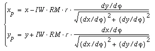
(6-8)