Classification of Cam Mechanisms
We can classify cam mechanisms by the modes of input/output motion, the configuration and arrangement of the follower, and the shape of the cam. We can also classify cams by the different types of motion events of the follower and by means of a great variety of the motion characteristics of the cam profile.
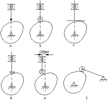
Figure 6-2 Classification of cam mechanisms
Modes of Input/Output Motion
- Rotating cam-translating follower. (Figure 6-2a,b,c,d,e)
- Rotating follower (Figure 6-2f):
The follower arm swings or oscillates in a circular arc with respect to the follower pivot. - Translating cam-translating follower (Figure 6-3).
- Stationary cam-rotating follower:
The follower system revolves with respect to the center line of the vertical shaft.
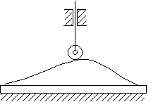
Figure 6-3 Translating cam - translating follower
6.2.1 Follower Configuration
- Knife-edge follower (Figure 6-2a)
- Roller follower (Figure 6-2b,e,f)
- Flat-faced follower (Figure 6-2c)
- Oblique flat-faced follower
- Spherical-faced follower (Figure 6-2d)
6.2.2 Follower Arrangement
- In-line follower:
The center line of the follower passes through the center line of the camshaft. - Offset follower:
The center line of the follower does not pass through the center line of the cam shaft. The amount of offset is the distance between these two center lines. The offset causes a reduction of the side thrust present in the roller follower.
6.2.3 Cam Shape
- Plate cam or disk cam:
The follower moves in a plane perpendicular to the axis of rotation of the camshaft. A translating or a swing arm follower must be constrained to maintain contact with the cam profile. - Grooved cam or closed cam (Figure 6-4):
This is a plate cam with the follower riding in a groove in the face of the cam.
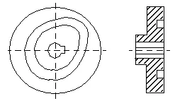
Figure 6-4 Grooved cam
- Cylindrical cam or barrel cam (Figure 6-5a):
The roller follower operates in a groove cut on the periphery of a cylinder. The follower may translate or oscillate. If the cylindrical surface is replaced by a conical one, a conical cam results. - End cam (Figure 6-5b):
This cam has a rotating portion of a cylinder. The follower translates or oscillates, whereas the cam usually rotates. The end cam is rarely used because of the cost and the difficulty in cutting its contour.
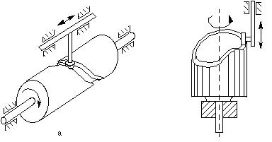
Figure 6-5 Cylindrical cam and end cam
6.2.4 Constraints on the Follower
- Gravity constraint:
The weight of the follower system is sufficient to maintain contact. - Spring constraint:
The spring must be properly designed to maintain contact. - Positive mechanical constraint:
A groove maintains positive action. (Figure 6-4 and Figure 6-5a) For the cam in Figure 6-6, the follower has two rollers, separated by a fixed distance, which act as the constraint; the mating cam in such an arrangement is often called a constant-diameter cam.
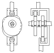
Figure 6-6 Constant diameter cam
A mechanical constraint cam also be introduced by employing a dual or conjugate cam in arrangement similar to what shown in Figure 6-7. Each cam has its own roller, but the rollers are mounted on the same reciprocating or oscillating follower.
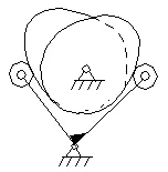
Figure 6-7 Dual cam
6.2.5 Examples in SimDesign
Rotating Cam, Translating Follower
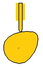
Figure 6-8 SimDesign translating cam
Load the SimDesign file simdesign/cam.translating.sim. If you turn the cam, the follower will move. The weight of the follower keeps them in contact. This is called a gravity constraint cam.
Rotating Cam/Rotating Follower
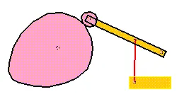
Figure 6-9 SimDesign oscillating cam
The SimDesign file is simdesign/cam.oscillating.sim. Notice that a roller is used at the end of the follower. In addition, a spring is used to maintain the contact of the cam and the roller.
If you try to calculate the degrees of freedom (DOF) of the mechanism, you must imagine that the roller is welded onto the follower because turning the roller does not influence the motion of the follower.