DIMENSIONS OF THE FLYWHEEL RIM
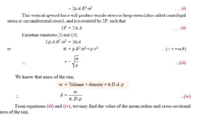
Consider a rim of the flywheel as shown in Fig. 16.17.
Let D = Mean diameter of rim in metres,
R = Mean radius of rim in metres,
A = Cross-sectional area of rim in m2,
ρ = Density of rim material in kg/m3,
N = Speed of the flywheel in r.p.m.,
ω = Angular velocity of the flywheel in rad/s,
v = Linear velocity at the mean radius in m/s
σ = Tensile stress or hoop stress in N/m2 due to the centrifugal force.
Consider a small element of the rim as shown shaded in Fig. 16.17. Let it subtends an angle δθ at the centre of the flywheel.
Volume of the small element
= A × R.δθ ∴ Mass of the small element
dm = Density × volume = ρ .A .R.δθ
and centrifugal force on the element, acting radially outwards, dF = dm.ω 2.R = ρ .A .R2.ω 2.δθ
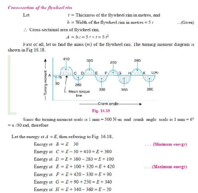
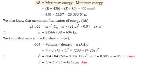
Q.The turning moment diagram for a multi-cylinder engine has been drawn to a scale of 1 mm to 500 N-m torque and 1 mm to 6° of crank displacement. The intercepted areas between output torque curve and mean resistance line taken in order from one end, in sq. mm are – 30, + 410, – 280, + 320, – 330, + 250, – 360, + 280, – 260 sq. mm, when the engine is running at 800 r.p.m.The engine has a stroke of 300 mm and the fluctuation of speed is not to exceed ± 2% of the mean speed. Determine a suitable diameter and cross-section of the flywheel rim for a limiting value of the safe centrifugal stress of 7 MPa. The material density may be assumed as 7200 kg/m3. The width of the rim is to be 5 times the thickness.
Solution. Given : N = 800 r.p.m. or ω = 2π × 800 / 60 = 83.8 rad/s; *Stroke = 300 mm ; σ = 7 MPa = 7 × 10 6 N/m2 ; ρ = 7200 kg/m3
Since the fluctuation of speed is ± 2% of mean speed, therefore total fluctuation of speed,
ω 1 – ω 2 = 4% ω = 0.04 ω


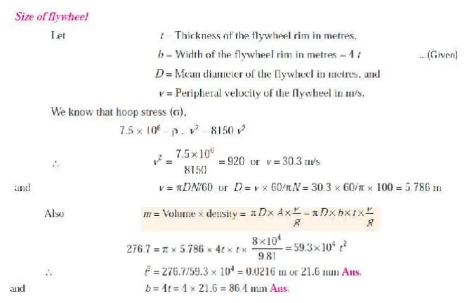
Q. The turning moment diagram of a four stroke engine may be assumed for the sake of simplicity to be represented by four triangles in each stroke. The areas of these triangles are as follows: Suction stroke = 5 × 10 –5 m2; Compression stroke = 21 × 10 –5 m2; Expansion stroke = 85 × 10 –5 m2; Exhaust stroke = 8 × 10 –5 m2.
All the areas excepting expression stroke are negative. Each m2 of area represents 14 MN-m of work.
Assuming the resisting torque to be constant, determine the moment of inertia of the flywheel to keep the speed between 98 r.p.m. and 102 r.p.m. Also find the size of a rim-type flywheel based on the minimum material criterion, given that density of flywheel material is 8150 kg/m3 ; the allowable tensile stress of the flywheel material is 7.5 MPa. The rim cross-section is rectangular, one side being four times the length of the other.
Solution. Given: a1 = 5 × 10 –5 m2; a2 = 21 × 10 –5 m2; a3 = 85 × 10 –5 m2; a4 = 8 × 10 –5 m2; N2 = 98 r.p.m.; N1 = 102 r.p.m.; ρ = 8150 kg/m3; σ = 7.5 MPa = 7.5 × 10 6 N/m2