FLYWHEEL
A flywheel used in machines serves as a reservoir, which stores energy during the period when the supply of energy is more than the requirement, and releases it during the period when the requirement of energy is more than the supply.
In case of steam engines, internal combustion engines, reciprocating compressors and pumps, the energy is developed during one stroke and the engine is to run for the whole cycle on the energy produced during this one stroke. For example, in internal combustion engines, the energy is developed only during expansion or power stroke which is much more than the engine load and no energy is being developed during suction, compression and exhaust strokes in case of four stroke engines and during compression in case of two stroke engines. The excess energy developed during power stroke is absorbed by the flywheel and releases it to the crankshaft during other strokes in which no energy is developed, thus rotating the crankshaft at a uniform speed. A little consideration will show that when the flywheel absorbs energy, its speed increases and when it releases energy, the speed decreases. Hence a flywheel does not maintain a constant speed, it simply reduces the fluctuation of speed. In other words, a flywheel controls the speed variations caused by the fluctuation of the engine turning moment during each cycle of operation.
In machines where the operation is intermittent like *punching machines, shearing machines, rivetting machines, crushers, etc., the flywheel stores energy from the power source during the greater portion of the operating cycle and gives it up during a small period of the cycle. Thus, the energy from the power source to the machines is supplied practically at a constant rate throughout the operation.
COEFFICIENT OF FLUCTUATION OF SPEED
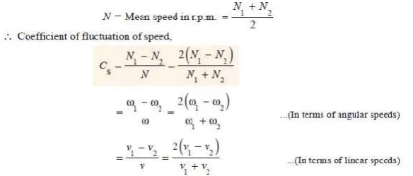
The difference between the maximum and minimum speeds during a cycle is called the maximum fluctuation of speed . The ratio of the maximum fluctuation of speed to the mean speed is called the coefficient of fluctuation of speed.
Let N1 and N2 = Maximum and minimum speeds in r.p.m. during the cycle, and
The coefficient of fluctuation of speed is a limiting factor in the design of flywheel. It varies depending upon the nature of service to which the flywheel is employed.
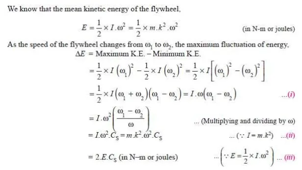
ENERGY STORED IN A FLYWHEEL
A flywheel is shown in Fig. 16.5. We have discussed in Art. 16.5 that when a flywheel absorbs energy, its speed increases and when it gives up energy, its speed decreases.
Let m = Mass of the flywheel in kg,
k = Radius of gyration of the flywheel in metres,

The radius of gyration (k) may be taken equal to the mean radius of the rim (R), because the thickness of rim is very small as compared to the diameter of rim. Therefore, substituting k = R, in equation (ii), we have

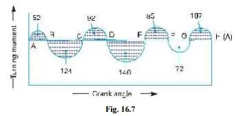
Q. The turning moment diagram for a multicylinder engine has been drawn to a scale 1 m m = 600 N -m vertically and 1 m m = 3° horizontally. The intercepted areas between the output torque curve and the mean resistance line, taken in order from one end, are as follows :
+ 52, – 124, + 92, – 140, + 85, – 72 and + 107 m m2, when the engine is running at a speed of 600 r.p.m. If the total fluctuation of speed is not to exceed (-+) 1.5% of the mean, find the necessary mass of the flywheel of radius 0.5 m.
Solution. Given : N = 600 r.p.m. or ω = 2 π × 600 / 60 = 62.84 rad / s ; R = 0.5 m
Since the total fluctuation of speed is not to exceed (-+) 1.5% of the mean speed, therefore ω 1 – ω 2 = 3% ω = 0.03 ω

Let the total energy at A = E, then referring to Fig. 16.7,
Energy at B = E + 52 ...(Maximum energy)
Energy at C = E + 52 – 124 = E – 72
Energy at D = E – 72 + 92 = E + 20
Energy at E = E + 20 – 140 = E – 120 ...(Minimum energy)
Energy at F = E – 120 + 85 = E – 35
Energy at G = E – 35 – 72 = E – 107
Energy at H = E – 107 + 107 = E = Energy at A
We know that maximum fluctuation of energy,
∆E = Maximum energy – Minimum energy
= (E + 52) – (E – 120) = 172 = 172 × 31.42 = 5404 N-m
Let m = Mass of the flywheel in kg. We know that maximum fluctuation of energy (∆ E ),

Q. A shaft fitted with a flywheel rotates at 250 r.p.m. and drives a machine. The torque of machine varies in a cyclic manner over a period of 3 revolutions. The torque rises from 750 N-m to 3000 N-m uniformly during 1/2 revolution and remains constant for the following revolution. It then falls uniformly to 750 N-m during the next 1/2 revolution and remains constant for one revolution, the cycle being repeated thereafter.
Determine the power required to drive the machine and percentage fluctuation in speed, if the driving torque applied to the shaft is constant and the mass of the flywheel is 500 kg with radius of gyration of 600 m m.
Solution. Given : N = 250 r.p.m. or ω = 2π × 250/60 = 26.2 rad/s ; m = 500 kg ; k = 600 mm = 0.6 m
The turning moment diagram for the complete cycle is shown in Fig. 16.8. We know that the torque required for one complete cycle
= Area of figure OABCDEF
=Area OAEF + Area ABG + Area BCHG + Area CDH
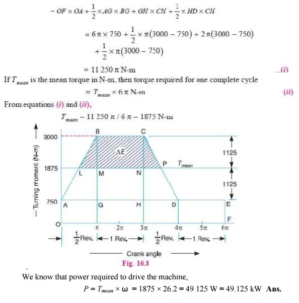
Power required to drive the machine
We know that power required to drive the machine,
P = Tmean × ω = 1875 × 26.2 = 49 125 W = 49.125 kW Ans.
Coefficient of fluctuation of speed
Let CS = Coefficient of fluctuation of speed.
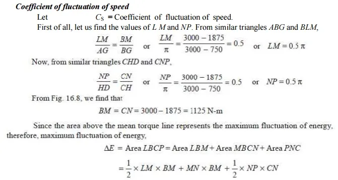
First of all, let us find the values of L M and NP. From similar triangles ABG and BLM,

Q. A single cylinder, single acting, four stroke gas engine develops 20 kW at 300 r.p.m. The work done by the gases during the expansion stroke is three times the work done on the gases during the compression stroke, the work done during the suction and exhaust strokes being negligible. If the total fluctuation of speed is not to exceed ± 2 per cent of the mean speed and the turning moment diagram during compression and expansion is assumed to be triangular in shape, find the moment of inertia of the flywheel.
Solution. Given : P = 20 kW = 20 × 10 3 W; N = 300 r.p.m. or ω = 2π × 300/60 = 31.42 rad/s
Since the total fluctuation of speed (ω 1 – ω 2) is not to exceed ± 2 per cent of the mean speed ), therefore
ω 1 – ω 2 = 4% ω
and coefficient of fluctuation of speed,

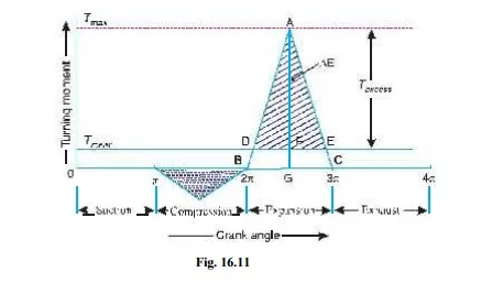
The turning moment-crank angle diagram for a four stroke engine is shown in Fig. 16.11. It is assumed to be triangular during compression and expansion strokes, neglecting the suction and exhaust strokes.
We know that for a four stroke engine, number of working strokes per cycle,
n = N/2 = 300 / 2 = 150
∴ Work done/cycle =P × 60/ n = 20 × 10 3 × 60/150 = 8000 N-m ------------(i)
Since the work done during suction and exhaust strokes is negligible, therefore net work done per cycle (during compression and expansion strokes)

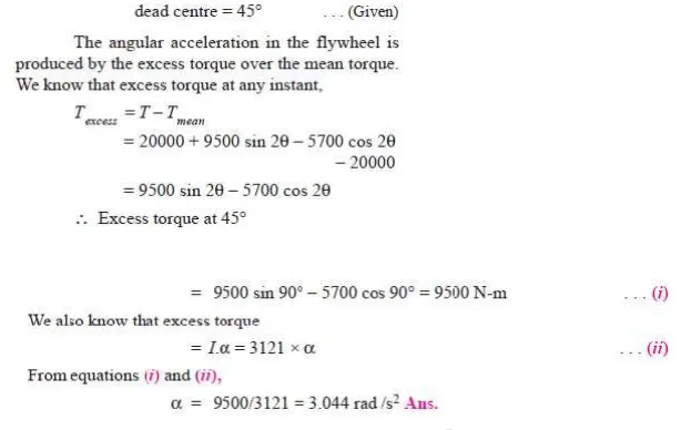
Q. The turning moment curve for an engine is represented by the equation, T = (20 000 + 9500 sin 2θ – 5700 cos 2θ ) N-m, where θ is the angle moved by the crank from inner dead centre. If the resisting torque is constant, find:
1. Power developed by the engine ; 2. Moment of inertia of flywheel in kg-m2, if the total fluctuation of speed is not exceed 1% of mean speed which is 180 r.p.m; and 3. Angular acceleration of the flywheel when the crank has turned through 45° from inner dead centre.
Solution. Given : T = (20 000 + 9500 sin 2θ – 5700 cos 2θ ) N-m ; N = 180 r.p.m. or
ω = 2π × 180/60 = 18.85 rad/s

2. Moment of inertia of the flywheel
Let I = Moment of inertia of the flywheel in kg-m2.
The turning moment diagram for one stroke (i.e. half revolution of the crankshaft) is shown in Fig. 16.13. Since at points B and D, the torque exerted on the crankshaft is equal to the mean resisting torque on the flywheel, therefore,

3. Angular acceleration of the flywheel
Let α = Angular acceleration of the flywheel, and θ = Angle turned by the crank from inner