Types of Shafts
Material Used for Shafts
The material used for shafts should have the following properties :
§ It should have high strength.
§ It should have good machinability.
§ It should have low notch sensitivity factor.
§ It should have good heat treatment properties.
§ It should have high wear resistant properties.
Types of Shafts
The following two types of shafts are important from the subject point of view :
1. Transmission shafts. These shafts transmit power between the source and the machines absorbing power. The counter shafts, line shafts, over head shafts and all factory shafts are transmission shafts. Since these shafts carry machine parts such as pulleys, gears etc., therefore they are subjected to bending in addition to twisting.
Machine shafts. These shafts form an integral part of the machine itself. The crank shaft is an example of machine shaft.
Stresses in Shafts
The following stresses are induced in the shafts :
· Shear stresses due to the transmission of torque (i.e. due to torsional load).
· Bending stresses (tensile or compressive) due to the forces acting upon machine elements like gears, pulleys etc. as well as due to the weight of the shaft itself.
· Stresses due to combined torsional and bending loads
Design of Shafts
The shafts may be designed on the basis of
Strength, and
Rigidity and stiffness.
In designing shafts on the basis of strength, the following cases may be considered :
Shafts subjected to twisting moment or torque only,
Shafts subjected to bending moment only,
Shafts subjected to combined twisting and bending moments, and
Shafts subjected to axial loads in addition to combined torsional and bending loads
Shafts Subjected to Bending Moment Only
When the shaft is subjected to a bending moment only, then the maximum stress (tensile or compressive) is given by the bending equation. We know that
M/I = σb/y
where M = Bending moment,
I = Moment of inertia of cross-sectional area of the shaft about the axis of rotation,
σb = Bending stress, and
y = Distance from neutral axis to the outer-most fibre.
Shafts Subjected to Twisting Moment Only
When the shaft is subjected to a twisting moment (or torque) only, then the diameter of the shaft may be obtained by using the torsion equation. We know that
T /J = τ/r
where T = Twisting moment (or torque) acting upon the shaft,
J = Polar moment of inertia of the shaft about the axis of rotation, τ = Torsional shear stress, and
r = Distance from neutral axis to the outer most fibre
d / 2; where d is the diameter of the shaft.
Shafts Subjected to Combined Twisting Moment and Bending Moment
When the shaft is subjected to combined twisting moment and bending moment, then the shaft
must be designed on the basis of the two moments simultaneously. Various theories have been suggested to account for the elastic failure of the materials when they are subjected to various types of combined stresses. The following two theories are important from the subject point of view:
Maximum shear stress theory or Guest's theory. It is used for ductile materials such as mild steel.
Maximum normal stress theory or Rankine’s theory. It is used for brittle materials such as cast iron.
Let τ = Shear stress induced due to twisting moment, and
σb = Bending stress (tensile or compre ssive) induced due to bending moment.
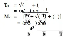
Shafts Subjected to Fluctuating Loads
In the previous articles we have assumed that the shaft is subjected to constant torque and bending moment. But in actual practice, the shafts are subjected to fluctuating torque and bending moments. In order to design such shafts like line shafts and counter shafts, the combined shock and fatigue factors must be taken into account for the computed twisting moment (T ) and bending moment (M ). Thus for a shaft subjected to c ombined ben ding and torsion, the equivalent twisting moment,