DC Machine
The DC machine can be classified into two types namely DC motors as well as DC generators. Most of the DC machines are equivalent to AC machines because they include AC currents as well as AC voltages in them. The output of the DC machine is DC output because they convert AC voltage to DC voltage. The conversion of this mechanism is known as the commutator, thus these machines are also named as commutating machines. DC machine is most frequently used for a motor. The main benefits of this machine include torque regulation as well as easy speed. The applications of the DC machine is limited to trains, mills, and mines. As examples, underground subway cars, as well as trolleys, may utilize DC motors. In the past, automobiles were designed with DC dynamos for charging their batteries.
A DC machine is an electromechanical energy alteration device. The working principle of a DC machine is when electric current flows through a coil within a magnetic field, and then the magnetic force generates a torque which rotates the dc motor. The DC machines are classified into two types such as DC generator as well as DC motor. The main function of the DC generator is to convert mechanical power to DC electrical power, whereas a DC motor converts DC power to mechanical power. The AC motor is frequently used in the industrial applications for altering electrical energy to mechanical energy. However, a DC motor is applicable where the good speed regulation & ample range of speeds are necessary like in electric-transaction systems.
DC Machine
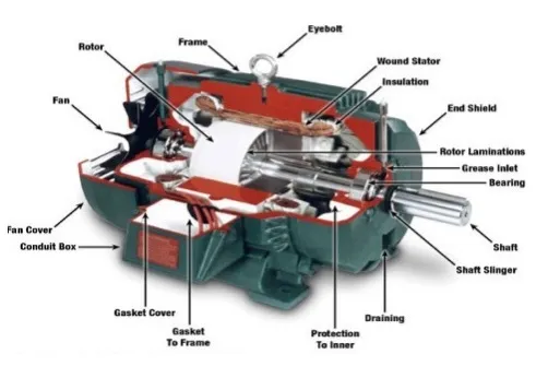
The construction of DC machine can be done using some of the essential parts like Yoke, Pole core & pole shoes, Pole coil & field coil, Armature core, Armature winding otherwise conductor, commutator, brushes & bearings. Some of the parts of the DC machine is discussed below.
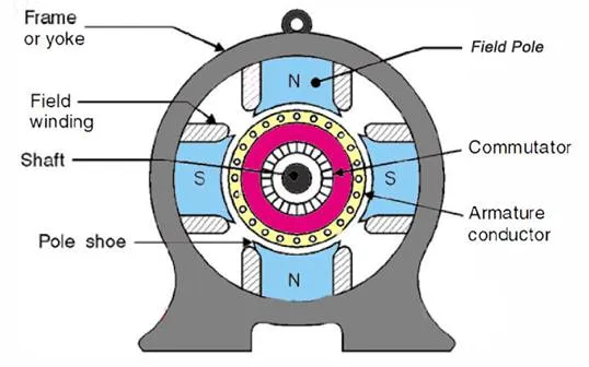
Construction of DC Machine
Another name of a yoke is the frame. The main function of the yoke in the machine is to offer mechanical support intended for poles and protects the entire machine from the moisture, dust, etc. The materials used in the yoke are designed with cast iron, cast steel otherwise rolled steel.
The pole of the DC machine is an electromagnet and the field winding is winding among pole. Whenever field winding is energized then the pole gives magnetic flux. The materials used for this are cast steel, cast iron otherwise pole core. It can be built with the annealed steel laminations for reducing the power drop because of the eddy currents.
Pole shoe in DC machine is an extensive part as well as enlarge the region of the pole. Because of this region, flux can be spread out within the air-gap as well as extra flux can be passed through the air space toward armature. The materials used to build pole shoe is cast iron otherwise cast steed, and also used annealed steel lamination to reduce the loss of power because of eddy currents.
In this, the windings are wounded in the region of pole core & named as field coil. Whenever current is supplied through field winding then it electromagnetics the poles which generate required flux. The material used for field windings is copper.
Armature core includes the huge number of slots within its edge. Armature conductor is located in these slots. It provides the low-reluctance path toward the flux generated with field winding. The materials used in this core are permeability low-reluctance materials like iron otherwise cast. The lamination is used to decrease the loss because of the eddy current.
The armature winding can be formed by interconnecting the armature conductor. Whenever an armature winding is turned with the help of prime mover then the voltage, as well as magnetic flux, gets induced within it. This winding is allied to an exterior circuit. The materials used for this winding are conducting material like copper.
The main function of the commutator in the DC machine is to collect the current from the armature conductor as well as supplies the current to the load using brushes. And also provides uni-directional torque for DC-motor. The commutator can be built with a huge number of segments in the edge form of hard drawn copper. The Segments in the commutator are protected from thin mica layer.
Brushes in the DC machine gather the current from commutator and supplies it to exterior load. Brushes wear with time to inspect frequently. The materials used in brushes are graphite otherwise carbon which is in rectangular form.
The excitation of the DC machine is classified into two types namely separate excitation, as well as self-excitation. In separate excitation type of dc machine, the field coils are activated with a separate DC source. In self-excitation type of dc machine, the flow of current throughout the field-winding is supplied with the machine. The principal kinds of DC machine are classified into four types which include the following.
· Separately excited DC machine
· Shunt wound/shunt machine.
· Series wound/series machine.
· Compound wound / compound machine.
In Separately Excited DC Machine, a separate DC source is utilized for activating the field coils.
In Shunt wound DC Machines, the field coils are allied in parallel through the armature. As the shunt field gets the complete o/p voltage of a generator otherwise a motor supply voltage, it is normally made of a huge number of twists of fine wire with a small field current carrying.
In series wound D.C. Machines, the field coils are allied in series through the armature. As series field winding gets the armature current, as well as the armature current is huge, due to this the series field winding includes few twists of wire of big cross-sectional region.
A compound machine includes both the series as well as shunt fields. The two windings are carried-out with every machine pole. The series winding of the machine includes few twists of a huge cross-sectional region, as well as the shunt windings, include several fine wire twists.
The connection of the compound machine can be done in two ways. If the shunt-field is allied in parallel by the armature only, then the machine can be named as the ‘short shunt compound machine’ & if the shunt-field is allied in parallel by both the armature as well as series field, then the machine is named as the ‘long shunt compound machine’.
The DC machine e.m.f can be defined as when the armature in the dc machine rotates, the voltage can be generated within the coils. In a generator, the e.m.f of rotation can be called the generated emf, and Er=Eg. In the motor, the emf of rotation can be called as counter or back emf, and Er=Eb.
Let Φ is the useful flux for every pole within webers
P is the total number of poles
z is the total number of conductors within the armature
n is the rotation speed for an armature in the revolution for each second
A is the no. of parallel lane throughout the armature among the opposite polarity brushes.
Z/A is the no. of armature conductor within series for each parallel lane
As the flux for each pole is ‘Φ’, every conductor slashes a flux ‘PΦ’ within a single revolution.
The voltage produced for each conductor = flux slash for each revolution in WB / Time taken for a single revolution within seconds
As ‘n’ revolutions are completed within a single second and 1 revolution will be completed within a 1/n second. Thus the time for a single armature revolution is a 1/n sec.
The standard value of produced voltage for each conductor
p Φ/1/n = np Φ volts
The voltage produced (E) can be decided with the no.of armature conductors within series I any single lane among the brushes thus, the whole voltage produced
E = standard voltage for each conductor x no. of conductors within series for each lane
E = n.P.Φ x Z/A
The above equation is the e.m.f. the equation of the DC machine.
We know that the main function of a DC machine is to convert mechanical energy to electrical energy. Throughout this conversion method, the whole input power cannot be changed into output power because of the power loss in different forms. The type of loss may change from one apparatus to another. These losses will decrease the apparatus efficiency as well as the temperature will be increased. The DC machine energy losses can be classified into Electrical otherwise Copper losses, Core losses otherwise Iron losses, Mechanical losses, Brush losses, and Stray load losses.