Types of Electrical Circuits
DC Circuits
In DC Circuits, the excitation applied is a constant source. Based on the type of connection of active and passive components with the source, a circuit can be classified into Series and Parallel circuits.
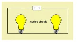
Series Circuits
When several passive elements are connected in series with an energy source, such a circuit is known as a series circuit. For a series circuit, same amount of current flows through each element and voltage is divided. In series circuit, as the elements are connected in a line,if there is faulty element among them ,complete circuit acts as open circuit.
· For a resistor connected in DC circuits, the voltage across its terminals is directly proportional to the current passing through it, thus maintaining a linear relationship between the voltage and current. For resistors connected in series, the total resistance is equal to the sum of all resistance values.
· For capacitors connected in series, the total capacitance is equal to the sum of reciprocals of all capacitance values.
· For inductors connected in series, total inductance is equal to the sum of all inductance values.
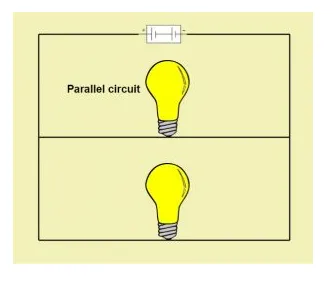
Parallel Circuits
In a parallel circuit, one terminal of all the elements is connected to the one terminal of the source and the other terminal of all elements is connected to the other terminal of the source.
In parallel circuits, the voltage remains the same in the parallel elements while the current changes. If there is any faulty element among parallel elements there is no effect on the circuit.
· For resistors connected in parallel, the total resistance is equal to the sum of reciprocals of all resistance values.
· For capacitors connected in series, the total capacitance is equal to the sum of all capacitance values.
· For inductors connected in series, total inductance is equal to the sum of all reciprocals of inductance values.
AC circuits
Ac circuits are those circuits, Whose excitation element is an AC source. Unlike DC source which is constant AC source has variable current and voltage at regular intervals of time. Generally, for high power applications, AC circuits are used.
Simple AC Circuit using resistance
For alternating current passing through the resistor, the ratio of current and voltage depends upon the phase and frequency of the supply. The applied voltage will change constantly with time and Ohm’s law can be used to calculate current passing through the resistor at any instant of time.
In other words, if at time t seconds, the value of voltage is v volts, current will be:
i = v/R
where the value of R is always constant.
Above equation shows that polarity of current depends upon that of the voltage. Also, both current and voltage reach their maximum and zero points at the same time. Thus, for a resistor, voltage is in phase with the applied current.
Consider the below circuit diagram

When the switch is closed, current passes through the resistor and is given by the below equation
i=Im cos(ωt+Φ)
Voltage,V=IR=RIm cos(ωt+Φ)
For a resistor, both voltage and current values will rise and fall at the same time. Hence, the phase difference between voltage and current is zero.
AC Circuit using pure inductance
A coil of thin wire wrapped on a cylindrical core is known as an Inductor. The core can be an air core (hollow laminated) or an iron core. As alternating current flows through the inductor, the magnetic field also changes. This change in magnetic field results in an induced voltage across the inductor. As per Lenz law, the induced voltage is such that it opposes the flow of current through it.
During the first half cycle of the source voltage, the inductor stores energy in form of magnetic field and in the next half, it releases energy.
The induced EMF is given as below
e=Ldi/dt
Here, L is the self-inductance.
Now, Input AC voltage applied is given as v(t)=Vm Sinωt
Current through the inductor is:I(t)=Im Sinωt

So, the voltage across the inductor would be
e=L di/dt=wLI_m coswt=wLI_m sin(wt+90)
Thus, for an inductor, voltage leads the current by 90 degrees.
Now, resistance by an inductor is termed as Reactance and given by
Thus, impedance or resistance is proportional to rate of change of current for an inductor.
AC Circuit with a capacitor
For a constant DC supply, the capacitor plates charge up to the applied voltage, stores this charge temporarily and then starts discharging. Once a capacitor is fully charged, it blocks the flow of current as the plates get saturated.

When AC supply voltage is applied to a capacitor, the rate of charging and discharging depends upon the supply frequency. Voltage across the capacitor lags the current flowing through it by 90 degrees.
Current through the capacitor is given as
e = Ldi/dt
The capacitive reactance is given as:
e = Ld/idt
Thus, impedance or reactance to AC supply is inversely proportional to the frequency of supply.