General characteristics of wheel suspensions
The suspension of modern vehicles need to satisfy a number of requirements whose aims partly conflict because of different operating conditions (loaded/ unloaded, acceleration/braking, level/uneven road, straight running/cornering). The forces and moments that operate in the wheel contact area must be directed into the body.
The kingpin offset and disturbing force lever arm in the case of the longitudinal forces, the castor offset in the case of the lateral forces, and the radial load moment arm in the case of the vertical forces are important elements whose effects interact as a result of, for example, the angle of the steering axis.
Sufficient vertical spring travel, possibly combined with the horizontal movement of the wheel away from an uneven area of the road (kinematic wheel) is required for reasons of ride comfort. The recession suspension should also be compliant for the purpose of reducing the rolling stiffness of the tyres and short-stroke movements in a longitudinal direction resulting from the road surface (longitudinal compliance, Fig.), but without affecting the development of lateral wheel forces and hence steering precision, for which the most rigid wheel suspension is required. This requirement is undermined as a result of the necessary flexibility that results from disturbing wheel movements generated by longitudinal forces arising from driving and braking operations.
For the purpose of ensuring the optimum handling characteristics of the vehicle in a steady state as well as in a transient state, the wheels must be in a defined position with respect to the road surface for the purpose of generating the necessary lateral forces. The build-up and size of the lateral wheel forces are determined by specific toe-in and camber changes of the wheels depending on the jounce and movement of the body as a result of the axle kinematics (roll steer) and operative forces (compliance steer). This makes it possible for specific operating conditions such as load and traction to be taken into consideration. By establishing the relevant geometry and kinematics of the axle, it is also possible to prevent the undesirable diving or lifting of the body during braking or accelerating and to ensure that the vehicle does not exhibit any tendency to oversteer and displays predictable transition behaviour for the driver.
Other requirements are:
· independent movement of each of the wheels on an axle (not guaranteed in the case of rigid axles);
· small, unsprung masses of the suspension in order to keep wheel load fluctuation as low as possible (important for driving safety);
· the introduction of wheel forces into the body in a manner favourable to the flow of forces;
· the necessary room and expenditure for construction purposes, bearing in mind the necessary tolerances with regard to geometry and stability; ease of use;
· behaviour with regard to the passive safety of passengers and other road users;
· costs.
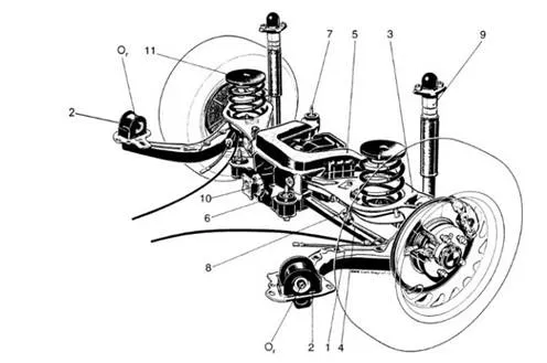
A multi-link rear axle – a type of suspension system which is progressively replacing the semi-trailing arm axle, and consists of at least one trailing arm on each side. This arm is guided by two (or even three) transverse control arms . The trailing arm simultaneously serves as a wheel hub carrier and (on four-wheel steering) allows the minor angle movements required to steer the rear wheels. The main advantages are, however, its good kinematic and elastokinematic characteristics. BMW calls the design shown in the illustration and fitted in the 3-series (1997) a ‘central arm axle’. The trailing arms 1 are made from GGG40 cast iron; they absorb all longitudinal forces and braking moments as well as transfering them via the points 2 – the centres of which also form the radius arm axes – on the body. The lateral forces generated at the centre of tyre contact are absorbed at the subframe 5, which is fastened to the body with four rubber bushes (items 6 and 7) via the transverse control arms 3 and 4. The upper arms 3 carry the minibloc springs 11 and the joints of the anti-roll bar 8. Consequently, this is the place where the majority of the vertical forces are transferred between the axle and the body. The shock absorbers, which carry the additional polyurethane springs 9 at the top, are fastened in a good position behind the axle centre at the ends of the trailing arms. For reasons of noise, the differential 10 is attached elastically to the subframe 5 at three points (with two rubber bearings at the front and one hydro bearing at the back). When viewed from the top and the back, the transverse control arms are positioned at an angle so that, together with the differing rubber hardness of the bearings at points 2, they achieve the desired elastokinematic characteristics. These are:
Ø toe-in under braking forces;
Ø lateral force compliance understeer during cornering;
Ø prevention of torque steer effects ;
Ø lane change and straight running stability.
For reasons of space, the front eyes 2 are pressed into parts 1 and bolted to the attachment bracket. Elongated holes are also provided in this part so toe-in can be set. In the case of the E46 model series (from 1998 onwards), the upper transverse arm is made of aluminium for reasons of weight (reduction of unsprung masses).