Electronic ignition control
An engine must be provided with fuel and air in correct proportions and the means to ignite this mixture in the form of an electric spark. Before the development of electronic ignition the traditional ignition system included spark plugs, a distributor, and a high-voltage ignition coil. The distributor would sequentially connect the coil output high voltage to the correct spark plug. In addition, it would cause the coil to generate the spark by interrupting the primary current (ignition points) in the desired coil, thereby generating the required spark. The time of occurrence of this spark (i.e., the ignition timing) in relation of the piston to top dead center (TDC) influences the torque generated.
In most present-day electronically controlled engines the distributor has been replaced by multiple coils. Each coil supplies the spark to either one or two cylinders. In such a system the controller selects the appropriate coil and delivers a trigger pulse to ignition control circuitry at the correct time for each cylinder. (Note: In some cases the coil is on the spark plug as an integral unit.)
Fig. a illustrates such a system as an example of a 4-cylinder engine. In this example a pair of coils provides the spark for firing two cylinders for each coil. Cylinder pairs are selected such that one cylinder is on its compression stroke while the other is on exhaust. The cylinder on compression is the cylinder to be fired (at a time somewhat before it reaches TDC). The other cylinder is on exhaust.
The coil fires the spark plugs for these two cylinders simultaneously. For the former cylinder, the mixture is ignited and combustion begins for the power stroke that follows. For the other cylinder (on exhaust stroke), the combustion has already taken place and the spark has no effect.
Although the mixture for modern emission-regulated engines is constrained by emissions regulations, the spark timing can be varied in order to achieve optimum performance within the mixture constraint. For example, the ignition timing can be chosen to produce the best possible engine torque for any given operating condition. This optimum ignition timing is known for any given
Distributorless ignition system
engine configuration from studies of engine performance as measured on an engine dynamometer.
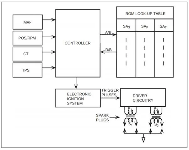
Fig. above is a schematic of a representative electronic ignition system. In this example configuration the spark advance (SA) value is computed in the main engine control (i.e., the controller that regulates fuel). This system receives data from the various sensors (as described above with respect to fuel control) and determines the correct SA for the instantaneous operating condition.
The variables that influence the optimum spark timing at any operating condition include RPM, manifold pressure (or MAF), barometric pressure, and CT. The correct ignition timing for each value of these variables is stored in an ROM lookup table. For example, the variation of SA with RPM for a representative engine is shown in Fig. below The engine control system obtains readings from the various sensors and generates an address to the lookup table (ROM). After reading the data from the lookup tables, the control system computes the correct SA. An output signal is generated at the appropriate time to activate the spark

In the configuration depicted in Fig. 1st, the electronic ignition is implemented in a stand-alone ignition module. This solid-state module receives the correct SA data and generates electrical signals that operate the coil driver circuitry. These signals are produced in response to timing inputs coming from crankshaft and camshaft signals (POS/RPM).
The coil driver circuits generate the primary current in windings P1 and P2 of the coil packs depicted in 1st Fig. These primary currents build up during the so-called dwell period before the spark is to occur. At the correct time the driver circuits interrupt the primary currents via a solid-state switch. This interruption of the primary current causes the magnetic field in the coil pack to drop rapidly, inducing a very high voltage (20,000–40,000 volts) that causes a spark. In the example depicted in 1st Fig. a pair of coil packs, each firing two spark plugs, is shown. Such a configuration would be appropriate for a 4-cylinder engine. Normally there would be one coil pack for each pair of cylinders.
The ignition system described above is known as a distributorless ignition system (DIS) since it uses no distributor. There are a number of older car models on the road that utilize a distributor. However, the electronic ignition system is the same as that shown in 1st Fig, up to the coil packs. In distributor-equipped engines there is only one coil, and its secondary is connected to the rotary switch (or distributor).
In a typical electronic ignition control system, the total spark advance, SA (in degrees before TDC), is made up of several components that are added together:
![]()
The first component, SAS, is the basic SA, which is a tabulated function of RPM and MAP. The control system reads RPM and MAP, and calculates the address in ROM of the SAS that corresponds to these values. Typically, the advance of RPM from idle to about 1200 RPM is relatively slow. Then, from about 1200 to about 2300 RPM the increase in RPM is relatively quick. Beyond 2300 RPM, the increase in RPM is again relatively slow. Each engine configuration has its own SA characteristic, which is normally a compromise between a number of conflicting factors.
The second component, SAP, is the contribution to SA due to manifold pressure. This value is obtained from ROM lookup tables. Generally speaking, the SA is reduced as pressure increases.
The final component, SAT, is the contribution to SA due to temperature. Temperature effects on SA are relatively complex, including such effects as cold cranking, cold start, warm-up, and fully warmed-up conditions.