Engine warm-up
While the engine is warming up, an enriched air/fuel ratio is still needed to keep it running smoothly, but the required air/fuel ratio changes as the temperature increases. Therefore, the fuel control system stays in the open-loop mode, but the air/fuel ratio commands continue to be altered due to the temperature changes. The emphasis in this control mode is on rapid and smooth engine warm-up. Fuel economy and emission control are still a secondary concern.
A diagram illustrating the lookup table selection of desired air/fuel ratios is shown in Fig. below. Essentially, the measured CT is converted to an address for the lookup table. This address is supplied to the ROM table via the system address bus (A/B). The data stored at this address in the ROM are the desired (A/F )d for that temperature. These data are sent to the controller via the system data bus (D/B).
There is always the possibility of a CT failure. Such a failure could result in excessively rich or lean mixtures, which can seriously degrade the performance of both the engine and the three-way catalytic converter (3wcc). One scheme that can circumvent a temperature sensor failure involves having a time function to limit the duration of the engine warm-up mode. The nominal time to warm the engine from cold soak at various temperatures is known. The controller is configured to switch from engine warm-up mode to an open-loop (warmed-up engine) mode after a sufficient time by means of an internal timer.
It is worthwhile at this point to explain how the quantity of fuel to be injected is determined. This method is implemented in essentially all operating modes and is described here as a generic method, even though each engine control scheme may vary somewhat from the following. The quantity of fuel to be injected during the intake stroke of any given cylinder (which we call F ) is determined by the mass of air (A) drawn into that cylinder (i.e., the air charge) during that intake
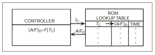
Illustration of lookup table for desired air/fuel ratio
stroke. That quantity of fuel is given by the air charge divided by the desired air/fuel ratio:
![]()
The quantity of air drawn into the cylinder, A, is computed from the MAF rate and the RPM. The MAF rate will be given in kg/sec. If the engine speed is RPM, then the number of revolutions/second (which we call r) is:
![]()
Then, the MAF is distributed approximately uniformly to half the cylinders during each revolution. If the number of cylinders is N then the air charge (mass) in each cylinder during one revolution is:
![]()
In this case, the mass of fuel delivered to each cylinder is:
![]()
This computation is carried out by the controller continuously so that the fuel quantity can be varied quickly to accommodate rapid changes in engine operating condition. The fuel injector pulse duration T corresponding to this fuel quantity is computed using the known fuel injector delivery rate Rf .
![]()
This pulse width is known as the base pulse width. The actual pulse width used is modified from this according to the mode of operation at any time.