Control modes for fuel control
The engine control system is responsible for controlling fuel and ignition for all possible engine operating conditions. However, there are a number of distinct categories of engine operation, each of which corresponds to a separate and distinct operating mode for the engine control system. The differences between these operating modes are sufficiently great that different software is used for each. The control system must determine the operating mode from the existing sensor data and call the particular corresponding software routine.
For a typical engine, there are seven different engine operating modes that affect fuel control: engine crank, engine warm-up, open-loop control, closed-loop control, hard acceleration, deceleration, and idle. The program for mode control logic determines the engine operating mode from sensor data and timers.
In the earliest versions of electronic fuel control systems, the fuel metering actuator typically consisted of one or two fuel injectors mounted near the throttle plate so as to deliver fuel into the throttle body. These throttle body fuel injectors (TBFIs) were in effect an electromechanical replacement for the carburetor. Requirements for the TBFIs were such that they only had to deliver fuel at the correct average flow rate for any given MAF. Mixing of the fuel and air, as well as distribution to the individual cylinders, took place in the intake manifold system.
The more stringent exhaust emissions regulations of the late 1980s and the 1990s have demanded more precise fuel delivery than can normally be achieved by TBFI. These regulations and the need for improved performance have led to timed sequential port fuel injection (TSPFI). In such a system there is a fuel injector for each cylinder that is mounted so as to spray fuel directly into the intake of the associated cylinder. Fuel delivery is timed to occur during the intake stroke for that cylinder.
The digital engine control system requires sensors for measuring the engine variables and parameters. Referring to Fig. below, the set of sensors may include, for example, MAF, exhaust gas oxygen (EGO) concentration, and crankshaft angular position (CPS), as well as RPM, camshaft position (possibly a single reference point for each engine cycle), coolant temperature (CT), throttle plate angular position (TPS), intake air temperature, and exhaust pressure ratio (EPR) for EGR control.
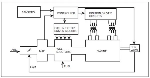
In the example configuration of Fig. below, fuel delivery is assumed to be TSPFI (i.e., via individual fuel injectors located so as to spray fuel directly into the intake port and timed to coincide with the intake stroke). Air flow measurement is via an MAF sensor. In addition to MAF, sensors are available for the measurement of EGO concentration, RPM, inlet air and CTs, throttle position, crankshaft (and possibly camshaft) position, and exhaust differential pressure (DP) (for EGR calculation). Some engine controllers involve vehicle speed sensors and various switches to identify brake on/off and the transmission gear, depending on the particular control strategy employed.
When the ignition key is switched on initially, the mode control logic automatically selects an engine start control scheme that provides the low air/fuel ratio required for starting the engine. Once the engine RPM rises above the cranking value, the controller identifies the ‘‘engine started’’ mode and passes control to the program for the engine warm-up mode. This operating mode keeps the air/fuel ratio low to prevent engine stall during cool weather until the engine CT rises above some minimum value. The instantaneous air/fuel is a function of CT. The particular value for the minimum CT is specific to any given engine and, in particular, to the fuel metering system. (Alternatively, the low air/fuel ratio may be maintained for a fixed time interval following start, depending on start-up engine temperature.)
When the CT rises sufficiently, the mode control logic directs the system to operate in the open-loop control mode until the EGO sensor warms up enough to provide accurate readings. This condition is detected by monitoring the EGO sensor’s output for voltage readings above a certain minimum rich air/fuel mixture voltage set point. When the sensor has indicated rich at least once and after the engine has been in open loop for a specific time, the control mode selection logic selects the closed-loop mode for the system. (Note: other criteria may also be used.) The engine remains in the closed-loop mode until either the EGO sensor cools and fails to read a rich mixture for a certain length of time or a hard acceleration or deceleration occurs. If the sensor cools, the control mode logic selects the open-loop mode again.
During hard acceleration or heavy engine load, the control mode selection logic chooses a scheme that provides a rich air/fuel mixture for the duration of the acceleration or heavy load. This scheme provides maximum torque but relatively poor emissions control and poor fuel economy regulation as compared with a stoichiometric air/fuel ratio. After the need for enrichment has passed, control is returned to either open-loop or closed-loop mode, depending on the control mode logic selection conditions that exist at that time.
During periods of deceleration, the air/fuel ratio is increased to reduce emissions of HC and CO due to unburned excess fuel. When idle conditions are present, control mode logic passes system control to the idle speed control mode. In this mode, the engine speed is controlled to reduce engine roughness and stalling that might occur because the idle load has changed due to air conditioner compressor operation, alternator operation, or gearshift positioning from park/neutral to drive, although stoichiometric mixture is used if the engine is warm.
In modern engine control systems, the controller is a special-purpose digital computer built around a microprocessor. A block diagram of a typical modern digital engine control system is depicted in Fig. below. The controller also includes ROM containing the main program (of several thousand lines of code) as well as rRAM for temporary storage of data during computation. The sensor signals are connected to the controller via an input/output (I/O) subsystem. Similarly, the I/O subsystem provides the output signals to drive the fuel injectors (shown as the fuel metering block of Fig. below) as well as to trigger pulses to the ignition system (described later in this chapter). In addition, this solid-state control system includes hardware for sampling and analog-to-digital conversion such that all sensor measurements are in a format suitable for reading by the microprocessor.
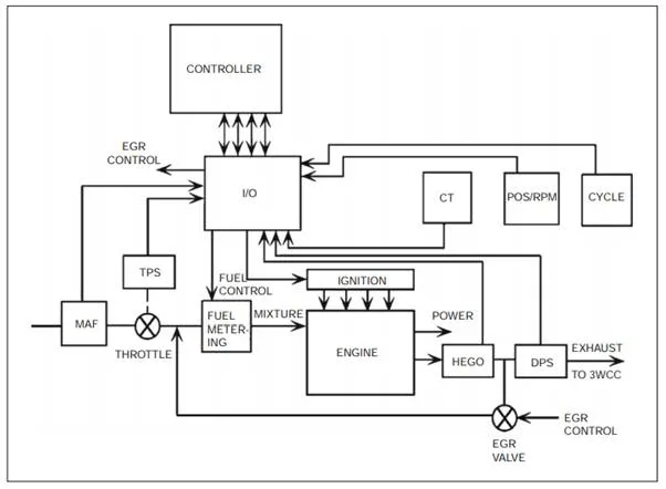
Digital engine control system diagram.
The sensors that measure various engine variables for control are as follows:
MAF:- Mass air flow sensor
CT :- Engine temperature as represented by coolant temperature
HEGO:- (One or two) heated EGO sensor(s)
POS/RPM:- Crankshaft angular position and RPM sensor cycle camshaft position sensor for determining start of each engine cycle
TPS:- Throttle position sensor
DPS:- Differential pressure sensor (exhaust to intake) for EGR control
The control system selects an operating mode based on the instantaneous operating condition as determined from the sensor measurements. Within any given operating mode the desired air/fuel ratio (A/F )d is selected. The controller then determines the quantity of fuel to be injected into each cylinder during each engine cycle. This quantity of fuel depends on the particular engine operating condition as well as the controller mode of operation, as will presently be explained.