Digital engine control features
The primary purpose of the electronic engine control system is to regulate the mixture (i.e., air–fuel), the ignition timing, and EGR. Virtually all major manufacturers of cars sold in the United States (both foreign and domestic) use the three-way catalyst for meeting exhaust emission constraints. For such cars, the air/fuel ratio is held as closely as possible to the stoichiometric value of about 14.7 for as much of the time as possible. Ignition timing and EGR are controlled separately to optimize performance and fuel economy.
Fig. below illustrates the primary components of an electronic engine control system. In this figure, the engine control system is a microcontroller, typically implemented with a specially designed microprocessor and operating under program control. Typically, the controller incorporates hardware multiply and ROM. The hardware multiply greatly speeds up the multiplication operation required at several stages of engine control relative to software multiplication routines, which are generally cumbersome and slow. The associated ROM contains the program for each mode as well as calibration parameters and lookup tables. The earliest such systems incorporated 8-bit microprocessors, although the trend is toward implementation with 32-bit microprocessors. The microcontroller under program control generates output electrical signals to operate the fuel injectors so as to maintain the desired mixture and ignition to optimize performance. The correct mixture is obtained by regulating the quantity of fuel delivered into each cylinder during the intake stroke in accordance with the air mass.
In determining the correct fuel flow, the controller obtains a measurement or estimate of the mass air flow (MAF) rate into the cylinder. The measurement is obtained using an MAF sensor. Alternatively, the MAF rate is estimated (calculated) using the speed–density method. This estimate can be found from measurement of the intake manifold absolute pressure (MAP), the revolutions per minute (RPM) and the inlet air temperature.
Using this measurement or estimate, the quantity of fuel to be delivered is determined by the controller in accordance with the instantaneous control mode. The quantity of fuel delivered by the fuel injector is determined by the operation of the fuel injector. A fuel injector is essentially a solenoid-operated valve. Fuel that is supplied to each injector from the fuel pump is supplied to each fuel injector at a regulated fuel pressure. When the injector valve is opened, fuel flows at a rate Rf (in gal/sec) that is determined by the (constant) regulated pressure and by the geometry of the fuel injector valve. The quantity of fuel F delivered to any cylinder is proportional to the time T that this valve is opened:
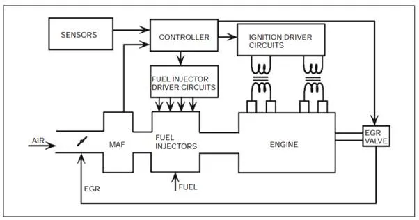
Components of an electronically controlled engine
F = RfT
The engine control system, then, determines the correct quantity of fuel to be delivered to each cylinder (for a given operating condition) via measurement of MAF rate. The controller then generates an electrical signal that opens the fuel injector valve for the appropriate time interval T to deliver this desired fuel quantity to the cylinder such that a stoichiometric air/fuel ratio is maintained.
The controller also determines the correct time for fuel delivery to correspond to the intake stroke for the relevant cylinder.