
What is aliasing?
Sampled data systems including ADCs and DACs must conform to the Nyquist criteria which states that the device must be sampled at greater than two times the highest frequency present at the input. If the Nyquist criteria is violated by sampling at too low a frequency, undesired spurious signals will appear in the frequency passband of the filter (Figure 1).
Figure 1: Aliasing results when the sample rate is less than twice the bandwidth of the input signal. Signal components from the lower sideband image about the sampling frequency are heterodyned into the baseband signal, resulting in distortion which cannot be removed. (Image source: Digi-Key Electronics)
The upper figure shows a time domain signal (left) sampled at a frequency that is greater than twice the signal bandwidth. The frequency domain view on the right shows the baseband signal from DC to fBW is separated from the lower sideband image about the sampling frequency fS.
The lower figures show an aliased condition. The time domain signal (left) is sampled below twice the signal bandwidth in violation of the Nyquist criteria. In the frequency spectrum (right) the sampling frequency has moved to the left reflecting a lower sampling rate. The lower sideband of the image about the sampling clock now overlaps the baseband signal contaminating its spectrum with spurious signals. Once this happens the original signal is no longer recoverable.
There are two commonly used methods to prevent aliasing. One can bandlimit the input to an ADC using a low pass filter. This is where the SCF comes in. It is also possible to increase the sample rate enough to guarantee that the sample rate greatly exceeds the input signals bandwidth.
SCFs configured as low pass filters do an admirable job of preventing aliasing; but they too are sampled data systems and so must conform to the Nyquist criteria. However, SCFs avoid aliasing by requiring the sampling frequency to be fifty to one hundred times the bandwidth of the input signal. This provides adequate guard band to prevent aliasing. If a lower sampling frequency is used, then a simple anti-aliasing filter can be used ahead of the SCF to prevent aliasing. In most cases these filters can be as simple as a single pole RC low pass filter.
Switched capacitor versus continuous time filter
It’s easy to compare SCFs to continuous time filters using a simple single pole RC low pass filter (Figure 2).
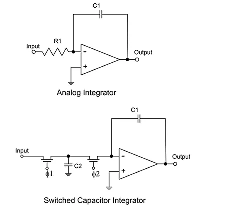
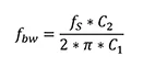
Figure 2: Comparing a continuous time RC low pass filter with an SCF, showing that the switched capacitor acts as a resistor. (Image source: Digi-Key Electronics)
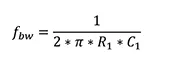
The top schematic shows a simple single pole RC low pass filter. The -3 decibel (dB) bandwidth is expressed as Equation 1:
Low frequency filter cutoffs will require large resistance values. If such a resistor were to be incorporated into a monolithic IC, the tolerance of resistance would be on the order of 20% to 50%.
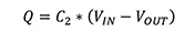
The lower schematic in Figure 1 is a switched capacitor implementation of the same low pass filter. The switches S1 and S2 are driven by the non-overlapping clocks j1 and j2 which have a frequency of fS. S1 first connects the input capacitor C2 to the input VIN. Then S1 opens and S2 is closed allowing C2 to share its charge with C1. The charge transferred from the input (VIN) to the output (VOUT) is calculated using Equation 2:
The average current flowing from the input to the output is the time integral of the charge, as shown in Equation 3:
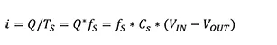
This is an Ohm’s law statement of the current through the switched capacitor circuit. From this statement the equivalent resistance is calculated using Equation 4:
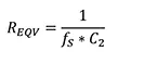
So, for a clock frequency of 200 kilohertz (kHz) and a switched capacitor value of 5 picofarads (pF), the equivalent resistance is 1 megaohm (MΩ).
Substituting this equivalent resistance into the equation for the bandwidth of the single pole low pass filter we get the SCF version shown in Equation 5:
In the switched capacitor configuration, the bandwidth depends upon the sampling or clock frequency, as well as the ratio of the switched capacitor C2 to the integrating capacitor C1. In a monolithic IC structure the resistors are replaced by small value capacitors and switches. Both of these components are relatively easy to incorporate into the IC, taking up only a small area on the chip.
The cutoff frequency of the filter is proportional to the sampling clock frequency so the clock can be used to tune the filter, which is an important feature in terms of flexibility. Using a high quality source for the sampling clock guarantees the accuracy and stability of the clock frequency, and thereby the filter’s corner frequency.
Note also that the cutoff frequency is proportional to the ratio of capacitance values which can be held to the tolerance level of <0.1% in an IC structure. Temperature changes affect the capacitors simultaneously and the ratio tends to remain constant.
Switched capacitor filter building blocks
Filters are built around reactive elements configured as integrators. In general, the filter design gains a pole for each integrator. Switched capacitors replace the resistor elements in the analog integrator design (Figure 3).
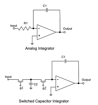
Figure 3: The switched capacitor replaces the resistor in an analog integrator. Switch elements are realized using CMOS FETs driven by a two-phase clock. (Image source: Digi-Key Electronics)
The switched capacitor is used to replace the resistor in an analog integrator. Switching is accomplished using two CMOS FETs driven by the non-overlapping j1 and j2 clocks.
In practice, analog filters like the two pole universal state variable design, can be executed as CMOS switched capacitor filters (Figure 4).
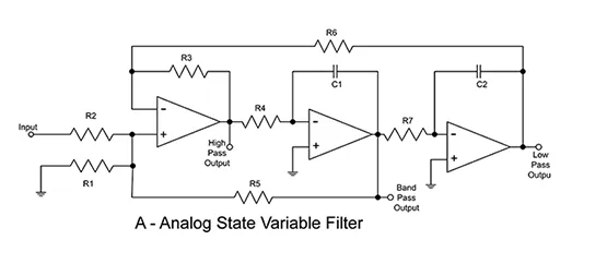
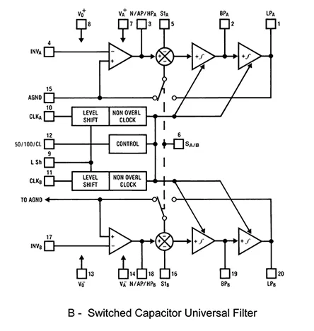
Figure 4: Comparison of a two pole state variable universal filter to a SCF. Both are universal filters offering high pass, low pass, and bandpass outputs (Image sources: Digi-Key Electronics (A) and Texas Instruments (B))
The SCF (B) is actually the functional block diagram of Texas Instruments’ MF10CCWMX/NOPB dual universal SCF. Like the analog state variable filter, it contains two integrator stages per section. In this case they are switched capacitor integrators. Each section can implement a two pole second order filter with a maximum cutoff frequency of 30 kHz. Concatenating the two sections permits realization of a fourth order filter in a single IC package. It does not require any external capacitors, only resistors. It requires a clock at either 50 or 100 times the desired cutoff frequency.
An example of SCF implementation uses both sections of the MF10 to create a 1 KHz low pass filter (Figure 5).
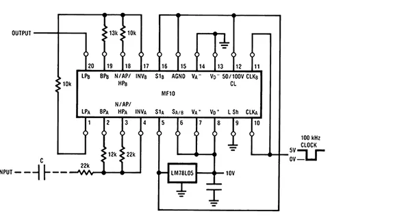
Figure 5: A fourth order 1 kHz low pass filter implemented using the MF10 SCF IC. (Image source: Texas Instruments)
The integration and switched capacitors are all internal to the 20-pin IC. The only external components used to set the filters’ characteristics are resistors. This circuit design configures the MF10 using a single 10 volt supply. The clock frequency is 100 times the 1 kHz cutoff frequency.
Designing with SCFs
Suppliers may offer design tools to speed the design phase. An example is Analog Devices’ LTC1060 dual universal filter building block IC, which is supported in the company’s LTspice XVII simulation program (Figure 6).

Figure 6: The design of a 4 pole low pass filter modeled in Analog Devices’ LTspice XVII, showing the schematic and the frequency/phase response plots. (Image source: Digi-Key Electronics)
Analog Devices includes a spice model for the LTC1060 filter building block. It is a dual, universal SCF IC that operates up to 30 kHz with a maximum clock rate of 500 kHz. Each of the filter sections contains two integrators providing two poles per section. With its six operating modes, it can be configured as a low pass, high pass, bandpass, or band stop filter. The design example combines both sections of the IC to create a 4 pole 200 Hz low pass filter with a 10 kHz clock. The design uses only seven resistors and no capacitors or inductors.
In addition to these universal filters, there are SCFs available with specific filter types. Bessel, Butterworth, elliptic, and linear phase filter configurations are available from the major suppliers.
Conclusion
As shown, SCFs offer precise spectral control that is easily implemented on an integrated circuit. They provide performance, size and cost improvements over analog RC based filters, and in the case of active filters, they do so without the need for external reactive components. A powerful advantage is that the filter’s frequency characteristics can be changed in real time by varying the clock frequency.