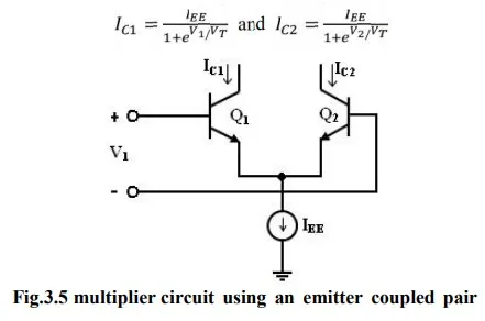
Analog multiplier using an Emitter coupled Transistor pair
The output currents IC1 an d IC2 are related to the differential input voltage V1 by
where V is thermal voltage and the base currents have been neglected. Combining above eqn., difference between=the two output− currents as

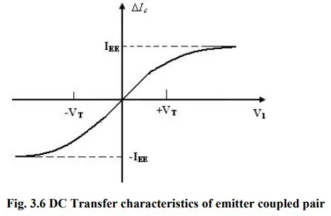
The dc transfer characteristics of the emitter – coupled pair is shown in figure. It shows that the emitter coupled pair can be used as a simple multiplier using this configuration. When the differential input voltage V1 << VT, we can appropriate as given by
∆IC =IEE ( V1/2VT)
The current IEE is the bias current for the emitter – coupled pair. If the current IEE is made proportional to a second input signal V2, then
IEE =K0 (V2 - VBE)/2VT
Substituting above eqn. , we get ∆IC = K0V1 (V2 - VBE)/2VT
This arrangement is shown in figure. It is a simple modulator circuit constructed using a differential amplifier. It can be used as a multiplier, provided V1 is small and much less than 50mV and V2 is greater than VBE (on). But, the multiplier circuit shown in figure has several limitations. The first limitation is that V2 is offset by VBE (on).
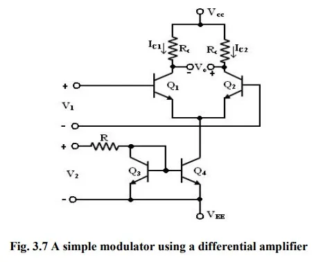
The second is that V2 must always be positive which results in only a two-quadrant multiplier operation. The third limitation is that, the tanh (X) is approximately as X, where X = V1 /2VT. The first two limitations are overcome in the Gilbert cell.