The Voltage Comparator
Although we can use operational amplifiers such as the 741 as a basic comparator circuit, the problem with this is that op-amps are only optimised for linear operation. That is where the input terminals are at virtually the same voltage level and its output stage is designed to produce a linear output voltage that is not saturated for long periods of time. Also standard operational amplifiers are designed to be used in closed-loop applications with negative feedback from its output to its inverting input.
A dedicated voltage comparator on the other hand is a non-linear device that allows for heavy saturation, due to its very high gain, when the input signals differs by a relatively small amount. The difference between an op-amp comparator and a voltage comparator is in the output stage as a standard op-amp has an output stage that is optimized for linear operation, while the output stage of a voltage comparator is optimized for continuous saturated operation as it is always intended to be close to one supply rail or the other and not in between.
Commercial comparators such as the LM311 single comparator, the LM339 quad comparator or the LM393 dual differential comparator, are voltage comparators which come in a standard IC package operating from a single or dual supply. These dedicated voltage comparators are designed for the sole purpose of switching the output very quickly from one saturated state the another as the transistors used for a voltage comparators output stage are generally switching transistors.
Since voltage comparators convert a linear input signal into a digital output signal, they are commonly used to connect two dissimilar electrical signals with different supply or reference voltages. As a result the output stage of the voltage comparator is generally configured as a single open collector (or Drain) transistor switch with open or closed states rather than actual output voltages as shown.
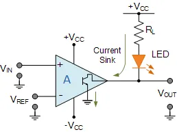
Voltage Comparator Circuit
Here, the open collector output from the voltage comparator is connected to a voltage source via a single pull-up resistor (and an LED for indication) which pulls the single output high to the power supply. When the output switch is HIGH it creates a high impedance path, therefore no current flows as VOUT = Vcc.
When the comparator changes state and the output switch is LOW, it creates a low impedance path to ground and current flows through the pull-up resistor (and LED) causing a voltage drop across itself with the output being pulled to the lower supply level, ground in this case.
Then we can see that there is very little difference between the schematic symbol of an op-amp comparator and a voltage comparator or their internal circuits. The main difference is in the output stage with the open collector or drain configuration is useful for driving relays, lamps, etc. By driving a transistor from the output allows for a greater switching current capacity than that of the comparators output alone.
Op-amp Comparator Summary
In this tutorial about the Op-amp Comparator we have seen that a comparator circuit is basically an operational amplifier without feedback, that is, the op-amp is used in its open-loop configuration, and when the input voltage, VIN exceeds a preset reference voltage, VREF, the output changes state.
Due to the very high open-loop gain of the operational amplifier, using it with positive feedback or even with no feedback at all causes the output to saturate to its supply rail producing one of two distinct output voltages depending on the relative values of its two inputs. This bistable behaviour is non-linear and forms the basis of op-amp comparator and Schmitt trigger circuits.
The output stages of dedicated comparators, such as the single LM311, the dual LM393 or the quad LM339 are designed to operate in their saturation regions allowing these voltage comparator circuits to be widely used in analogue-to-digital converter applications and for various types of voltage level detection circuits.
The erratic switching behaviour of an open-loop comparator can be easily overcome by adding positive feedback between the output and input of the comparator. With positive feedback, the circuit has hysteresis with the output switching occurring between two different switching points, UTP and LTP.
Op-amp window comparators are a type of voltage comparator circuit which uses two op-amp comparators to produce a two-state output that indicates whether or not the input voltage is within a particular range or window of values by using two reference voltages. An upper reference voltage and a lower reference voltage.
While operational amplifiers and comparators may look similar, they are very different and designed to be used in different applications as an op-amp may be used as a comparator, a voltage comparator can not be used as an op-amp due to its non-linear output stage.
We know from previous tutorials that an operational amplifier is an analogue device with a differential analogue input and an analogue output and if operated in its open-loop configuration its output acts like a comparator output. But dedicated voltage comparators (LM311, LM393, LM339) are widely available which will perform much better than a standard op-amp comparator.