Multivibrators
Multivibrators are sequential logic circuits that operate continuously between two distinct states of HIGH and LOW
Individual Sequential Logic circuits can be used to build more complex circuits such as Multivibrators, Counters, Shift Registers, Latches and Memories.
But for these types of circuits to operate in a “sequential” way, they require the addition of a clock pulse or timing signal to cause them to change their state. Clock pulses are generally continuous square or rectangular shaped waveform that is produced by a single pulse generator circuit such as a Multivibrator.
A multivibrator circuit oscillates between a “HIGH” state and a “LOW” state producing a continuous output. Astable multivibrators generally have an even 50% duty cycle, that is that 50% of the cycle time the output is “HIGH” and the remaining 50% of the cycle time the output is “OFF”. In other words, the duty cycle for an astable timing pulse is 1:1.
Sequential logic circuits that use the clock signal for synchronization are dependent upon the frequency and and clock pulse width to activate there switching action. Sequential circuits may also change their state on either the rising or falling edge, or both of the actual clock signal as we have seen previously with the basic flip-flop circuits. The following list are terms associated with a timing pulse or waveform.
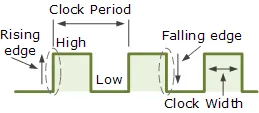
Clock Signal Waveform
§ Active HIGH – if the state change occurs from a “LOW” to a “HIGH” at the clock’s pulse rising edge or during the clock width.
§ Active LOW – if the state change occurs from a “HIGH” to a “LOW” at the clock’s pulses falling edge.
§ Duty Cycle – this is the ratio of the clock width to the clock period.
§ Clock Width – this is the time during which the value of the clock signal is equal to a logic “1”, or HIGH.
§ Clock Period – this is the time between successive transitions in the same direction, ie, between two rising or two falling edges.
§ Clock Frequency – the clock frequency is the reciprocal of the clock period, frequency = 1/clock period. ( ƒ = 1/T )
Clock pulse generation circuits can be a combination of analogue and digital circuits that produce a continuous series of pulses (these are called astable multivibrators) or a pulse of a specific duration (these are called monostable multivibrators). Combining two or more of multivibrators provides generation of a desired pattern of pulses (including pulse width, time between pulses and frequency of pulses).
There are basically three types of clock pulse generation circuits:
· Astable – A free-running multivibrator that has NO stable states but switches continuously between two states this action produces a train of square wave pulses at a fixed frequency.
· Monostable – A one-shot multivibrator that has only ONE stable state and is triggered externally with it returning back to its first stable state.
· Bistable – A flip-flop that has TWO stable states that produces a single pulse either positive or negative in value.
One way of producing a very simple clock signal is by the interconnection of logic gates. As NAND gates contains amplification, they can also be used to provide a clock signal or timing pulse with the aid of a single Capacitor and a single Resistor to provide the feedback and timing function.
These timing circuits are often used because of there simplicity and are also useful if a logic circuit is designed that has unused gates which can be utilised to create the monostable or astable oscillator. This simple type of RC Oscillator network is sometimes called a “Relaxation Oscillator”.