How to Make Gears with a CNC Machine
Download
There is an assortment of gears available for download on the Free G-code, CamBam, dxf, and stl Files page in case you don’t feel like going to the trouble of designing your own.
Material
I cut my gears out of 3/4 inch MDF, and they hold up quite well. I had one project where they were attached to an electric motor. After many hours of use, the gears showed almost no signs of wear. The teeth did seem as though they had been lightly sanded. All in all, they actually looked better then they did when first cut out. I’m sure they could have lasted for a lot longer, but the project was finished so I disassembled it.
Drawing a Gear in Sketchup
First, go up to the menu bar and click draw. Assuming you have the Involute Gear Plug-in installed, there will be two options for drawing gears: Involute Gear and Key Involute Gear. We’ll look at Involute Gear first.
Involute Gear
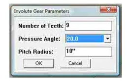
After you click Involute Gear, this window pops up. Let’s take a look at how each of these options will change the gear.
When choosing the number of teeth your gear will have, it’s not a bad idea to use numbers like 2, 4, 8, 16 32, 64, 128 …. The reason is for the simple fact that you can divide these numbers in half and get an even number. For example, if you were to make one gear with 31 teeth it would be possible to make another twice as big with 62 teeth but not one half as big because 31/2 = 15.5. You can’t make a gear with .5 of a tooth in Sketchup!
Other “easy” numbers to use are
3, 6, 12, 24 …
4, 8, 16, 32 …
5, 10, 20, 40 …
6, 12, 24, 48 …
Etc.
As you can see, starting out with a small number will give you a bigger selection of gear sizes.
The point is that you should think a bit before you go to the trouble of making a bunch of gears.
If your like me, you’ll end up with a box full of them, and it’s nice to have them all work with one another so that they can be used in different projects.
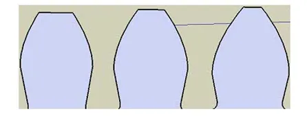
The picture below shows what changing the pressure angle does to the gear tooth.
On the left is 14.5 the middle is 20.0 and on the right is 25.0
[bad]
It won’t usually make much of a difference which you use, but I’ve always used the default setting of 20.0 without problems. Although, now that I can see each of these laid out, I think that 25.0 might be the best. A router bit is not able to cut all the way into corners because the bit itself has a certain dimension to it. Using the narrower 25.0 will help compensate for this fact. Like I said before though, it doesn’t usually make a difference.
Changing the pitch radius will make the gear either bigger or smaller. However, as you can see from the picture below, the size of the gear doesn’t come out exactly how you might expect it to.
Here, I made a gear with a pitch radius of 10″ and then drew a circle with a 10″ radius on top of it.
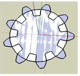
The gear is actually bigger than the circle which is something to keep in mind when designing one. It would be a shame if you went to a lot of effort to make a gear only to find out that it is bigger than you wanted it to be.