Basic Electrical Controls
Controls for conveyors and automation should be designed with emphasis on the requirements of the men who must keep the systems operating. The best approach is to have a system that will automatically stop safely in case of failure, and provide signals to pinpoint the area of the trouble. Usually more time is required to locate the cause of the failure than to correct it. Modern factory equipment is becoming more complex and diversified. Conveyors add to the complexity. It is difficult to recruit and train enough qualified maintenance people. If stoppages are frequent, maintenance men learn exactly what to do. The more reliable a piece of equipment is, the more important it is to spot troubles quickly. If maintenance personnel changes frequently, or if the regular maintenance man is away, the foreman or some other mechanic must take over. Then it is an advantage to have controls that are easy to understand, to maintain, and to service.
The cost of down time in modern plants is prohibitive. The savings of even a few minutes in restoring production operations will pay for a great deal of wiring and extra signals. It is sometimes difficult to sell this idea to purchasing departments or those with little experience in operating production machinery. Conveying systems cannot be installed in duplicate as is possible with machine tools. A stoppage at one point stops the whole system and all related operations.
For example, an automobile final assembly line may be set for 60 jobs an hour. One minute lost means bne car that may not be built that day. Union rules generally do not permit speedup to make up for lost time or production.
Joint Industry Conference (J.I.C.) Standards These standards provide an accepted guide for Materials Handling Control. The prime purposes of the standards are to:
1. Reduce maintenance and increase reliability.
2. Increase safety for operating and maintenance workers.
3. Reduce down time by making control functions easier to trace, understand, and repair.
Most companies try to standardize on only a few makes of motors and control components. This reduces their spare parts inventory. It is important to determine, in writing, just what will be acceptable in a particular plant.
Enclosures must be semi-dust-tight with gasketed openings. There can be no knockouts to open accidently or openings through which liquids or dust can enter. Since most control panels are custom designed, this requirement adds little to the cost. Disconnect switches must open both power and control circuits. Enclosure size and layout of components should permit installation later on of at least 15 or 20% more relays and terminals. This gives the engineer an opportunity to take care of inevitable errors or the requiremen~ of future changes in the field. Extra contacts on relays are good insurance. Relays with contacts interchangeable for either normally open or normally closed reduce costs.
Control voltage is usually specified as 110 volts a-c. There are many more components readily available and stocked for 110 volts a-c than any· other voltage. This voltage is high enough to ensure good contact and relay operation even with long control leads. Standard incandescent lamps can be used for local signals at emergency stop pushbuttons.
Panel Wiring. All external wires must come to numbered terminals in control panels. All internal wires must be marked with numbered labels on each end. All wires must be stranded and use acceptable crimped-on terminals. Color coding of wires for different functions is required. Fiber wiring channels with removable covers are preferable to laced cables for ease of installation, change, and tracing. Relays, push buttons, and other similar components in a control panel should be marked with labels corresponding to diagrams.
Relays should preferably be identical. Four pole relays will take care of nearly all normal conditions. If more poles are required, it is better to parallel added relays. Generally, industrial type relays have given little trouble, and provisions for plug-in types are not necessary. The principal difficulty with relays has been dirt in normally closed contacts.
Signals. Limit switches operated by machine parts or products are generally used for signals to control functions. The control engineer must work with the mechanical designer to be sure that limit switches can be located at the proper points. Frequently some mechanical part is already in the way when the field electrician starts to adjust limit switches. Then a compromise must be worked out either to change the original part or control diagram or both. It is recommended that limit switches be mounted on clamp-on brackets or in other ways to allow for plenty of adjustment. Switches should be designed so that accidental reversal cannot cause damage to the operating arms or plungers. Timing of operations is usually based on· the position of the limit switches.
Standard machine-tool type limit· switches either require too much movement to operate the contacts or have too little overtravel, or the operating arms are too short to work directly off conveyor parts. This requires additional operating arms and cams in special mountings. Some limit switches are designed especially for conveyor work. These have (a) heavy operating shafts turning in ball beari~gs, (b) extended arms up to 15 in. long, (c) shorter travel to operate, and (d) up to 90° total travel. This permits the arms to be made cam shaped so that switch operation will be the same regardless of the direction of travel of parts past the arm.
It is desirable to restrict the number of types of limit switches used on a system. Also, it is preferable not to use more than one normally open and one normally closed contact on a switch. If more contacts are required, use relays operated by limit switches. Each switch can be wired exactly the same with a 4-conductor cord and lock type cap so that prewired switches can be stocked. A permanently wired receptacle located near the switch position is wired for the correct connection used. Limit switches are more likely to fail mechanically than electrically. In case of failure, it is only necessary to remove and replace the faulty switch, plug it in, and adjust the operating arm to get the machine hack into operation.
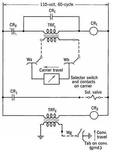
"Wiper" circuits have been developed to reduce problems of limit switches. Standard llO-volt relays are used in series with the primary of a specially designed transformer. The secondary of the transformer can be wound for 5 to 24 volts. With proper values in the transformer, its impedance, with the secondary open, will prevent the relay from picking up. When the secondary is shorted, its impedance is lowered, and the relay is energized. See Fig. 1.
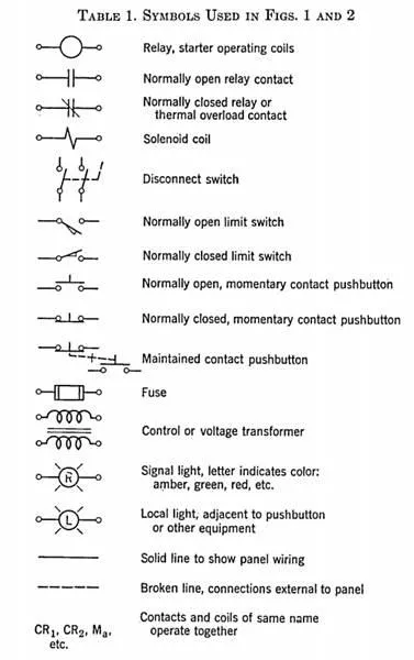
FIG. 1. Typical "wiper" circuit selector for conveyor carriers. Short circuiting secondary of transformer causes relays to energize. See Table 1 for symbols.
The secondary is connected to insulated wipers which are contacted by the conveyor parts. Two or more wipers can be connected by selectively controlled patterns of contacts for different combinations of signals. Or one side of the secondary can be grounded and one wiper can contact any metal part of the machine.
Wipers are plated steel springs supported at an angle of about 45° to the direction of travel by pivoted arms which lift clear if parts reverse. No movement is required for operation. This permits a variation of plus or minus ~ in. of contact alignment for positive contact. Voltage at the wipers is less than 24 volts, and it is safe to use exposed contacts. 'Vipers can be connected with simple open wiring. This reduces cost of installa tion.
This type of circuit is particularly adapted to automatic loading and unloading of overhead trolley conveyors and power-and-free conveyors. 'Vipers have long life and are cheap and easy to replace. The greater latitude for variations in operating positions reduces problems of field adjustment. Combinations for shorting the transformer are infinite.
Relay contacts and manual selector switches can be added in the secondary circuits.
Other means of providing signals include photoelectric relays, with or without modulated light, proximity limit switches using radio-frequency circuits and operated by absorption of energy by a passing metallic part, and magnetic pickup devices. These are usually more expensive and subject to failure of tubes and lamps. The elimination of physical contact warrants their use with proper safeguards in same applications.
Safety circuits should be designed to prev~nt damage to personnel or equipment. Hazards should be analyzed for the worst conditions. Emphasis should be on keeping machine running, 'and not stopping until the last possible moment. It may not be necessary to stop so often. This requires the machine to stop quickly on signal and indicates drive motor brakes. If a machine stops before parts jam, it is usually easy to clear. If parts are damaged, repair will require a costly down time.