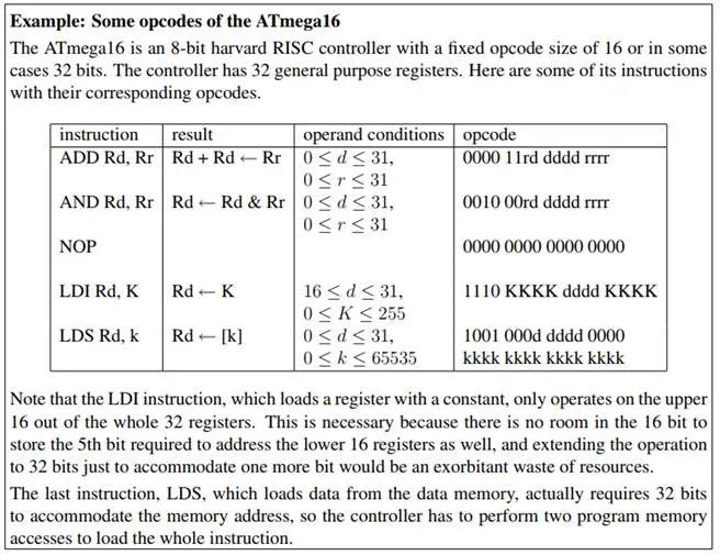
Instruction Size
An instruction contains in its opcode information about both the operation that should be executed and its operands. Obviously, a machine with many different instructions and addressing modes requires longer opcodes than a machine with only a few instructions and addressing modes, so CISC machines tend to have longer opcodes than RISC machines.
Note that longer opcodes do not necessarily imply that your program will take up more space than on a machine with short opcodes. As we pointed out in our CISC vs. RISC example, it depends on what you need. For instance, the 10 lines of ATmega16 RISC code require 20 byte of code (each instruction is encoded in 16 bits), whereas the 68030 instruction fits into 4 bytes. So here, the 68030 clearly wins. If, however, you only need instructions already provided by an architecture with short opcodes, it will most likely beat a machine with longer opcodes. We say “most likely” here, because CISC machines with long opcodes tend to make up for this deficit with variable size instructions. The idea here is that although a complex operation with many operands may require 32 bits to encode, a simple NOP (no operation) without any arguments could fit into 8 bits. As long as the first byte of an instructions makes it clear whether further bytes should be decoded or not, there is no reason not to allow simple instructions to take up only one byte. Of course, this technique makes instruction fetching and decoding more complicated, but it still beats the overhead of a large fixed-size opcode. RISC machines, on the other hand, tend to feature short but fixed-size opcodes to simplify instruction decoding.
Obviously, a lot of space in the opcode is taken up by the operands. So one way of reducing the instruction size is to cut back on the number of operands that are explicitly encoded in the opcode. In consequence, we can distinguish four different architectures, depending on how many explicit operands a binary operation like ADD requires:
Stack Architecture: This architecture, also called 0-address format architecture, does not have any explicit operands. Instead, the operands are organized as a stack: An instruction like ADD takes the top-most two values from the stack, adds them, and puts the result on the stack. Accumulator Architecture: This architecture, also called 1-address format architecture, has an accumulator which is always used as one of the operands and as the destination register. The second operand is specified explicitly.
2-address Format Architecture: Here, both operands are specified, but one of them is also used as the destination to store the result. Which register is used for this purpose depends on the processor in question, for example, the ATmega16 controller uses the first register as implicit destination, whereas the 68000 processor uses the second register.
3-address Format Architecture: In this architecture, both source operands and the destination are explicitly specified. This architecture is the most flexible, but of course it also has the longest instruction size.
Table 2.1 shows the differences between the architectures when computing (A+B)*C. We assume that in the cases of the 2- and 3-address format, the result is stored in the first register. We also assume that the 2- and 3-address format architectures are load/store architectures, where arithmetic instructions only operate on registers. The last line in the table indicates where the result is stored.
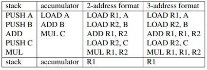
Table 2.1: Comparison between architectures.