Directional Control Valves, Switches and Gauges
Lesson Objectives
After learning the lesson students should be able to
• Describe the major types of direction control valves, their construction, operation and symbol
• Describe the major types of pressure relief and flow control valves, their construction, operation and symbol
• Describe pressure switches, as well as pressure and flow gauges used in hydraulic systems
Introduction
There are two basic types of hydraulic valves. Infinite position valves can take any position between fully open and fully closed. Servo valves and Proportional valves are in this category and are discussed in a separate lesson. Finite position valves can only assume certain fixed positions. In these positions the various inlet and outlet ports are either fully open or fully closed. However, depending on the position of the valve, particular inlet ports get connected to particular other outlet ports. Therefore flows in certain directions are established, while those in other directions are stopped. Since it is basically the directions of the flows that are controlled and not the magnitudes, these are called directional control valves.
Directional valves can be characterized depending on the number of ports, the number of directions of flow that can be established, number of positions of the valve etc. They are mainly classified in terms of the number of flow directions, such as one-way, two way or four-way valves. These are described below.
Directional valves are often operated in selected modes using hydraulic pressure from remote locations. Such mechanisms are known as pilots. Thus a valve that may be blocking the flow in a certain direction in absence of pilot pressure, may be allowing flow, when pilot pressure is applied. This enables one to build greater flexibility in the automation of system operation.
Check Valve
In its simplest form, a check valve is a one-way directional valve. It permits free flow in one direction and blocks flow in the other. As such is analogous to the electronic diode.
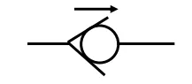
The Check Valve Symbol
The simple ball-and-seat symbol shown in Fig. 1 is used universally for denoting check valves although it is different from the way the other valves are denoted. The direction of the arrow shows the direction for free flow.
In its simplest form of construction, a check valve is realized as an in-line ball and spring as shown in Fig.
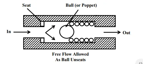
A check valve permits flow in one direction
Pressure from the left moves the ball from its seat so to permit unobstructed flow. Pressure from right pushes the ball tight on to the seat, and flow is blocked shown in Fig. In some valves a poppet is used in place of the ball. In some other construction, the valve inlet and outlet ports are made at right angles.
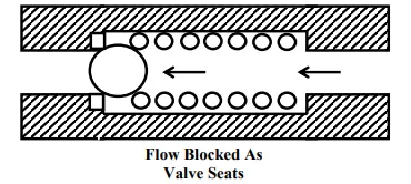
A Check Valve blocks flow in the reverse direction
Pilot – operated Check Valves
Pilot-operated check valves are designed to permit free flow in one direction and to block return flow, unless pilot pressure is applied. However, under pilot pressure, flow is permitted in both directions. They are used in hydraulic presses as prefill valves – to permit the main ram to fill by gravity during the “fast approach” part of the stroke. They also are used to support vertical pistons which otherwise might drift downward due to leakage past the directional valve spool.
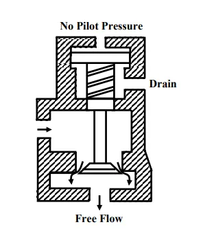
The construction of a pilot operated check valve is shown in Fig. With no pilot pressure, the valve functions as a normal check valve. Flow to bottom is permitted but the reverse is blocked. If pilot pressure is applied, the valve is open at all times, and flow is allowed freely in both directions as shown in Fig.
Unidirectional flow without pilot pressure
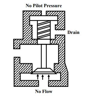
Unidirectional flow without pilot pressure
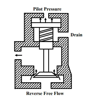
Reverse flow with pilot pressure
The check valve poppet has the pilot piston attached to the poppet stem. A light spring holds the poppet seated in a no-flow condition by pushing against the pilot piston. A separate drain port is provided to prevent oil from creating a pressure build up on the underside of the piston. Reverse flow can occur only when a pressure that can overcome the pressure in the outlet chamber is applied.
Possible application of the valve can be to permit free flow to the accumulator, while blocking flow out of it. If the pilot is actuated the accumulator can discharge if the pressure at the inlet port is lower than the accumulator pressure.
Point to Ponder: 1
A. Can you draw an inlet pressure flow characteristics of the ball type check valve?
B. What should be the nature of the spring used in the check valves, hard or soft?
Two-Way and Four-Way Valves
Two-way and four-way valves direct inlet flow from the pump to the system through either of two outlet ports. They typically have a pump port, usually denoted as P, a tank port denoted T, and ports denoted A, B, which are connected to the system. These are finite position valves. In each position the ports P and T are connected to the ports A and B in such a fashion that a particular direction of flow is established. Finite position valves generally have four ports. Finite position valve symbols are constructed from squares. Typical applications include control of lift tables, press push backs, or other low-pressure fluid devices.
These valves can be classified either as rotary or as spool valves, depending on the mechanism that creates the connections in the various positions of the valve. These are conceptually identical, only while the motion of the moving parts of the valve is rotational in the former and linear in the other. Therefore, in the sequel, mainly spool valves are discussed.
Rotary Valve
A rotary valve consists simply of a rotor closely fitted in a valve body. Passages in the rotor connect or block the ports in the valve body to provide the desired flow paths. They are used principally as pilot valves to control other valves.
Spool Type Valve
In the spool type directional valve a cylindrical spool moves back and forth in a machined bore in the valve body. The port connections in the body are interconnected through annular grooves in the spool or blocked by the raised portions of the spool called lands. Changes in valve operation are achieved by utilizing spools with different land patterns, with the same valve body.
Two-way valve
Fig represents, symbolically, a two-way valve where in one position the port P is connected to the load B while port A and port T are plugged. In the other position, the port P is connected to the load A while port B and T remain plugged. The valve moves its position from port A to port B and vice versa when force is applied to the spool, the port A is selected with the spool to the right and the port B with the spool to the left. Tank only serves to drain leakage from the valve
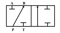
Symbol for a two-way valve
A two-way valve with the spool to the left
A two-way valve with the spool to the right
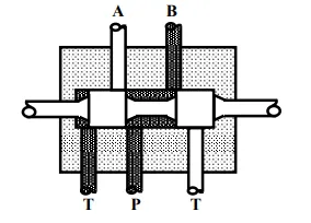
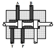
Four-way valve
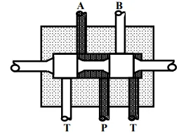
In two-way valves the pump port is connected to ports A and B in the two positions and the tank port serves only to drain leakage from within the valve. Thus the return flow does not take place through the valve. In the four-way valve the ports P and T are connected to the ports A and B, respectively, in one position, and to B and A respectively, in the other. Thus, both the flow from the pump and the return flow to the reservoir are directed through the valve.
Most of these valves are of the spool type. They are available both in two-position or three position versions. The three-position valve has a centre or neutral position. Methods of actuation include manually operated levers, cams and linkages, solenoids, hydraulic or pneumatic pilot pressure etc.
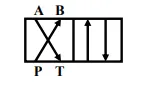
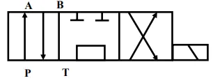
Symbol for a four-way valve
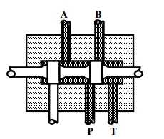
A four-way valve with the spool to the left A four-way valve with the spool to the left
Spool Centre Conditions
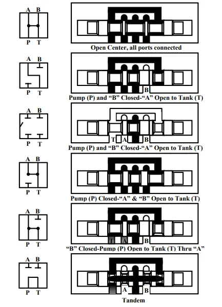
Various centre Configurations and their Symbols
Three-position valve spools provide identical flow patterns in the shifted positions but available with a variety of port connections configurations in the neutral position as illustrated in Figure 27.6. The open-centre spool interconnects all ports and the pump delivery can flow to tank at low pressure. The closed centre spool, on the other hand, has all ports blocked. This allows the pump delivery to be diverted to other parts of the circuit. Otherwise, it is to be diverted to tank through a relief valve. Other centre conditions permit various other configurations blocking and opening of ports.
Spools may be held in the center positions by centering springs, by spring-loaded detents or by oil under pressure. The terms “spring-centered” and “spring-offset” refer to the use of springs returning valve spools to their normal position. A spring centered valve is returned to the center position by spring force whenever the actuating effort is released. A spring-offset valve is a two-position valve returned to one extreme position by a spring whenever the actuating effort is released. It is shifted to the other position by one of the actuating methods mentioned above. A valve without a spring has to be actuated throughout the cycle by an external actuation, without which, it may “float” unless retained by detents or friction pads.
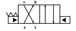
Operating Controls
As mentioned above, spool valves can be actuated in a number of ways. A typical manually operated four-way valve is shown with its graphical symbol in Figure 27.7a; a mechanically operated valve in Figure. Figure illustrates a spool type four-way valve that is shifted by air pressure against a piston at either end of the valve spool. A common method of actuating a small spool valve is with a solenoid as shown in Fig. 27.7d. Note that the appropriate controlling symbol is added with the basic valve symbol.
A solenoid operated three-position four-way directional valve symbol
In larger valves, the force required to shift the spool is more than what can be obtained practically from a solenoid. Large directional valves are, therefore, actuated by pilot pressure (Fig). The pilot pressure, in turn, can be directed from a hydraulic pressure source by a smaller four-way valve called a pilot valve, which may be actuated by a solenoid.
A solenoid operated three-position four-way directional valve symbol
Point to Ponder: 2
A. In Fig, what is the position of the valve when there is no pressure at both the pilot ports?
B. Is it possible to connect directional control valves in series and/or parallel? Can anything be achieved thereby? Are there conditions in which this is possible?
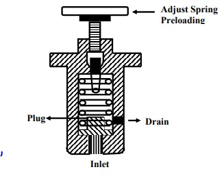
Relief Valves
Relief valves are used for regulation of pressure in hydraulic systems for protection of equipment and personnel. The simplest relief valve is the spring and plug arrangement of Fig. The spring keeps the valve shut until a pressure set by an adjustable spring tension is reached which pushes the spring up to relief the pressure by connecting the inlet to the drain
Relief valve
Fig is a symbol for a relief valve. The arrow on the spring shows adjustable tension. Pilot operated relief valves are shown with a dotted line and without a spring symbol.
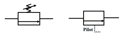
Relief valve symbols
Infinite position valves (example relief valves) have a single arrow. The arrow shows flow direction and are generally drawn in non-operated condition.
Pressure Switches
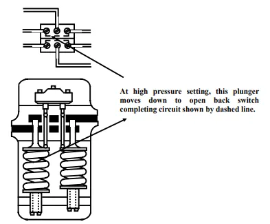
Pressure switches (Fig) are used to make or break (open or close) electrical circuits at selected pressures to actuate solenoid operated valves or other devices used in the system.
The operating principle of a pressure switch is shown in Figure. This design contains two separate electrical switches. Each is operated by a push rod which bears against a plunger whose position is controlled by hydraulic and spring forces. The pressure at which the switches operate is selected by turning the adjusting screw to increase or lessen the spring force.
It should be noted that in this design the switches are actuated by the springs when the unit is assembled. Thus the normally open contacts are closed and vice versa.
When the preset pressure is reached the plunger will compress the spring and allow the push rods to move down causing the snap action switches to revert to their normal condition.
By using both switches in conjunction with an electrical relay, system pressures may be maintained within widely variable high and low ranges.
Instruments
Flow rate, pressure and temperature measurements are required in evaluating the performance of hydraulic components. All three can be helpful too in setting up or trouble-shooting a hydraulic system. Due to the difficulty in installing a flow meter in the circuit, flow measurements are
often determined by timing the travel or rotation of an actuator. Pressure and temperature are determined in the usual manner by means of gauges and thermometers.
Pressure Gauges
Pressure gauges are needed for adjusting pressure control valves to required values and for determining the forces being exerted by a cylinder or the torque of a hydraulic motor. A typical pressure gauge used is a Bourdon tube. In the Bourdon tube gauge (Fig. 27.10), a sealed tube is formed in an arc. When pressure is applied is applied at the port opening, the tube tends to straighten. This actuates linkage to the pointer gear and moves the pointer to indicate the pressure on a dial. Most pressure gauges read zero at atmospheric pressure and are calibrated in pounds per square inch, ignoring atmospheric pressure throughout their range.
Pump inlet conditions are often less than atmospheric pressure. They would have to be measured as absolute pressure, sometimes referred to as psia, but more often calibrated in inches of mercury with 30 inches of mercury considered a perfect vacuum. A vacuum gauge calibrated in inches of mercury is shown in figure
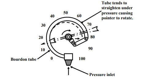
A C type Bourdon gauge
Flow Meters
Flow meters are coupled into the hydraulic piping to check the volumetric efficiency of a pump and determining leakage paths within the circuit.
A typical flow meter used is a rotameter, which consists of a weight in a calibrated vertical tube. Oil is pumped into the bottom and out the top and raises the weight to a height proportional to the flow. For more accurate measurement, a fluid motor of known displacement can be used to drive a tachometer.
More sophisticated measuring devices are turbine type flow meters which generate an electrical impulse as they rotate and pressure sensing transducers which may be located at strategic point within the system where they send out electrical signals proportional to the pressures encountered. These signals can be calibrated and observed on an oscilloscope or other readout devices.
Point to Ponder: 3
A. Consider the type 4 and type 6 centre conditions of the 3-position 4 way valve shown above. Imagine that a double acting hydraulic cylinder is connected across the ports A and B. Comment on the possible motion of the load when the valve is at the center
B. Can you justify, why the bourdon tube is perhaps the most suitable of the pressure sensor sin this application?
Lesson Summary
In this lesson we have dealt with the following topics
A. Basic types of direction control valves, such as one-way, two-way and four-way valves.
B. Introduced the concept of pilot operation of valves in the context of check valves and relief valves.
C. Described various center conditions as well as operating controls for four way valves. D. Described typical types of instruments and switches used in hydraulic circuits.