Higher Levels of Automation Systems
Instructional Objectives
After learning the lesson students should be able to
A. Describe the major functions of Production Management Systems under Level 3 Automation
B. Describe the major features of a Supervisory Control System under Level 2 Automation
C. Describe the major features of a Distributed Control System (DCS)
Introduction
The major activities that define the manufacturing enterprise in direct relation to the manufacturing of products include (i) Production Management, and (iii) Manufacturing. The first function is incorporated in Level 3 automation while the second one refers to Level 1 and Level 2 functions of a hierarchical Industrial Automation System. In the earlier lessons of this course we have predominantly been concerned with Level 1 Automation for manufacturing. In this lesson we briefly discuss these other aspects and particularly Level 2 and Level 3 Automation in more detail below. Finally, a typical implementation of the functionality of Level 2 and 3 automations, under the technological platform known as Distributed Control Systems (DCS).
Level 1 Automation: Production Management
The role of production management is to plan and control effectively the physical and operational resources of the manufacturing plant such as, materials, tools, fixtures, machines, storage space, material handling equipment, and manpower, so as to meet the production requirements. Production management is also referred to as Production Planning and Control. As the name implies, it comprises two functions, namely, Production Planning and Production Control.
Production planning is concerned with: (1) deciding on the set of products to be manufactured, along with their production volumes, over a certain duration which is called the planning horizon; (2) scheduling, i.e., determining the sequence of production of the set of parts and products over the time duration and (3) allocation of the necessary manpower, raw material and equipment resources needed to accomplish the production plan. Activities within the scope of production planning include the following.
Aggregate production planning.
This involves determination of the target production output levels. The word aggregate means that planning is conducted at a gross level to meet the total demand collected over all products consolidated into product groups, utilizing the total human, equipment and material resources. These plans must be made in cognizance of various functions of the firm other than manufacturing, such as product design, production, inventory, marketing, and sales for the plan to be feasible and effective for the overall business objectives of a firm. Further, it must be made based on an accurate forecast of the demand for the products.
Master production planning. In the next stage, the aggregate production plan must be detailed into a master production schedule (MPS), which includes specification of target production volumes of individual product types and their production schedules. In turn, this master schedule must be converted into purchase orders for raw materials, orders for subcontracting, and product schedules for subassemblies and components. These activities must sequence properly and coordinated to enable the delivery of the final product on schedule, under the existing resource constraints. Based on the MPS, one now carries out the allocation of production resources in the following two steps. Typical horizons for MPS may be of several months.
Material requirements planning (MRP) translates the MPS of end products into a detailed schedule for the procurement of raw materials and parts used in those end products. More precisely, MRP takes the master schedule data, bill of materials file, and the inventory data and determines when to order raw materials and components for assembled products. It can also reschedule orders in response to variations in production priorities and demand conditions.
Capacity planning is concerned with determining the labor and equipment resources needed to achieve the master schedule. Capacity planning can be carried out, either on a short-term or a long-term basis. Short-term capacity planning decisions include: overtime or reducing the workweek, hiring and firing, subcontracting, and inventory stockpiling. Long-term capacity planning includes decisions such as acquisition of new resources and manpower, augmentation or closure of facilities etc. Typically, capacity and materials plans are made for periods of weeks to a month.
Production control is concerned with providing for the necessary resources to implement the production plan. The major aspects of production planning include:
Shop floor control transforms the planning decisions into control commands for the production process. It also involves collection of data related to shop floor operations and processing and communication of the data on to higher control levels. Also termed as, Production Activity Control, it consists of three activities: order release, order scheduling, and order progress.
The purpose of the order release module is to provide the necessary documentation that accompanies an order as it is processed through the shop floor. This documentation consists of route sheet, material requisitions, job cards, parts list, etc.
Order scheduling involves assignments of orders to various machines and manufacturing units, so that the delivery schedules are met, in-process inventory is minimized, and machine utilization is maximized. Order scheduling involves two steps: (1) machine loading, and (2) job sequencing. Machine loading involves allocating jobs to machines, and job sequencing determines the order in which the jobs are processed through a work centre. Several priority rules could be used for job sequencing. These include shortest processing time, first-come-first-served, least slack, etc.
The purpose of the order progress module is to continuously acquire and communicate data relating to work-in-process and shop order status.
Inventory control. Inventory control is concerned with maintaining certain levels of stock for raw material, semi-finished parts, subassemblies, and finished goods. This is needed to create a buffer between the company and its suppliers and consumers and also between different stages of the manufacturing system. Such a buffer can provide insurance against machine failures, uncertain demands, uncertain suppliers, and worker absenteeism so that manufacturing activities do not get stalled. However, the inventory should be kept at an optimal low at the same time maintaining satisfactory customer service.
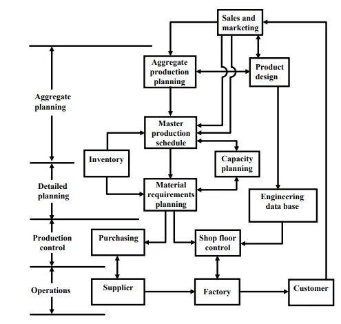
The activities in a modem PPC system and their interrelationships are depicted in Figure. A sophisticated automation system that combines MRP and capacity planning as well as shop floor control and other functions related to PPC is known as Manufacturing resource planning and a standard for the same is called MRP II. As the figure indicates, PPC ultimately extends to the company’s supplier base and customer base. This expanded scope of PPC is known as supply chain management.
Points to Ponder: 1
A. How is ERP (short for Enterprise Resource Planning), popular software based technology related to Level 3 automation?
B. The above description of Level 3 automation is given mainly in the context of discrete manufacturing. Do you expect different features for continuous manufacturing processes, such as a refinery or a steel plant?
Level 2 Automation: Supervisory Control
Supervisory control combines the firm’s production scheduling and management information functions with the process control functions to form a hierarchical control system. Figure 39.2 outlines a typical functional hierarchy of such an industrial computer control system. It should be noted that the several levels shown in fig are operational levels and do not necessarily represent separate and distinct computational hardware levels. In large systems a separate computer may be needed to handle each level, but in small systems, two or more operational levels might be collapsed into one computer level. The dedicated digital controllers at Level 1 require no human intervention since their functional tasks are completely fixed by systems design and are these are not interacted with, on-line, by operators. All other levels have human interfaces as indicated.
Activities for Production Planning and Control and their relationships with other functions in the firm, customers and suppliers
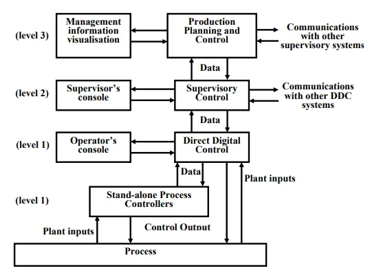
Functional hierarchy of an industrial control system
For a large manufacturing complex there, is need not only for vertical command/feedback communication among the levels, there is also need for horizontal level communications for coordination among automation systems for various units. Such communications are shown in Fig. The level 2 and level 3 automation functionalities are therefore split into two distinct blocks, namely, 2A/2B and 3A/3B. While the blocks 2A and 3A interact vertically within the same area control system, the blocks 2B and 3B interact horizontally across operational areas.
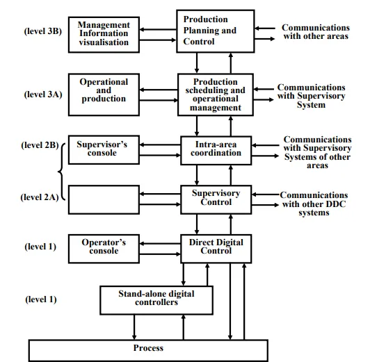
Functional hierarchy of a multi-area industrial control system
The Level 2 automation systems offer the following two main capabilities:
1. Tight optimized control of each operating unit of the plant based upon the production levels and constraints set by Level 3 PPC system by providing optimal operating set points to the manufacturing processes. This control reacts directly to any emergencies that occur in its own unit.
2. Improved overall reliability and availability of the total control system through fault detection, fault tolerance, redundancy, and other applicable techniques built into the system’s specification and operation.
Supervisory Control Tasks
In the context of a large industrial plant, the tasks carried out at each level of the hierarchy are as described in Table
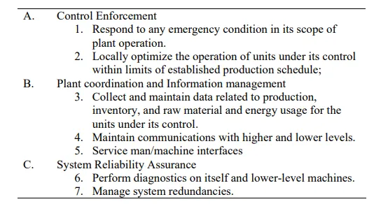
Table : Main tasks of the Supervisory Level
Details of how the operations are actually carried out will vary significantly, particularly at the lowest levels, because of the nature of the actual processes being controlled.
To perform the above tasks, the system must sample each important plant or process variable continuously. Plant variables are normally sampled at variable rates depending upon the type of variable being sensed, and the dynamics or speed of response of the process being and monitored and controlled. The sampled values of the variables are processed to compute diagnostic features, such as average/rms values and compared with a set of thresholds to detect the presence of any abnormal operating condition. These may also be compared with operating set point to compute controls.
In addition to being used for emergency detection and control corrections, the values of the process variables are stored in the computer’s memory in a process database. These data are then used for operator’s console read-out functions, for data logging for historical records, for process efficiency calculations, and for read-out to higher level computers for optimization calculations, inventory monitoring, overall plant production status and historical file updates, and other necessary calculations. An equally important task is to maintain the plant’s production data base for the company’s production, financial, and personnel reports.
Points to Ponder: 2
A. Note that while Level 1 automation is mostly free of human intervention, in Levels 2 and 3, appreciable human interaction with automation systems may be needed. Considering this what do you think would be some desirable features of man-machine interfaces for these levels?
B. “It can be said that Level 1 and Level 3 automation technology largely depends on the core technological areas of Process Data Analysis and Optimization.” Provide your comments on the above statement based upon studies of industrial applications
Finally, we discuss the technology platform that realizes the Level 1 and Level 2 automation, namely Distributed Control Systems (DCS)
Distributed Control Systems (DCS)
Brief History
Distributed control system (DCSs) have been evolving rapidly since the mid 1980s from being essentially panel board replacement at their inception to become comprehensive plant information, computing, and control networks fully integrated into the mainstream of plant operations. This progress has been fuelled in part by the technological revolution in microprocessor and software technology and in part, by economic necessity.
Microprocessor-based DCSs made their debut in the mid-1970s. Initially they were conceived as functional replacements for electronic panel board instrumentation and were packaged accordingly. The initial systems utilized discrete panel board displays similar to their electronic instrumentation counterparts. These systems evolved quickly, adding video-based workstations and shared controllers capable of expressing complex unit-operations-oriented regulatory and sequence control strategies containing scores of functional elements, such as PID (proportional integral-derivative), lad/lag/totalizers, dead-time elements, elapsed timer, logic circuits and general-purpose calculators
By the early to mid-1980s the personal computer industry matured into a multibillion dollar per year marked with the IBM PC disk operating system (DOS) as the standard. This gave birth to the software industry that delivered feature-laden high quality inexpensive software packages. The opportunity for system integrators and value-added resellers was clear. One could devolop an relatively-inexpensive scan control alarm, and data acquisition (SCADA) package for a personal computer platform and integrate it with these general-purpose shrink wrap software packages, such as spreadsheet, desktop publishing, or database management, and one could have a very cost-effective alternative to DCS. Because of performance and the general suitability limitations of these PC offerings, this approach had appeal mostly in cost-sensitive noncritical applications and where these existed a low safety or hazard risk. This concept, however, created an expectation and vision of the future, that is, open architectures.
DCS vendors felt a compulsion to enrich their arsenal of tools to address real-time process control applications by incorporating the low-cost shrink-wrap packages into their systems. Such packages included:
• Relational database management
• Spreadsheet packages
• Statistical process control capabilities
• Expert systems
• Computer-based process simulation
• Computer-aided design and drafting
• Desktop publishing
• Object-oriented display management
• Windows-oriented display management
Information exchange with other plant systems.
During the last 1980s and early 1990s the computer industry continued its transformation. Networking of systems into a cohesive whole promised to (again) revolutionize an industry, which has barely absorbed the impact of the PC revolution. Software and communications standard began to take hold, making interoperability among disparate computing platforms and application software a near-term reality. The business enterprise, including the factory floor, could be molded into a cohesive whole by making the various departmental systems work cooperatively at an acceptable integration cost. These added new technological features to DCS including:
• Open operating system standards, such as UNIXC ir POSIX
• Open system interconnect (OSI) communications model
• Client server cooperative computing model
• X-window protocols for workstation communications
• Distributed relational database management systems
• SQL access to distributed relational databases
• Object oriented programming and platform independent languages
• Computer-aided software engineering (CASE)
These characterize the modern DCS technology. DCSs, today are distributed computing platforms with sufficient performance to support large-scale real-time process applications. Structurally DCSs traditionally are organized into five major subsystems, namely (1) operations workstations that act as the MMI and provide visualisation capability, (2) controller subsystems that perform direct digital control, (3) data collection subsystems, (4) process computing subsystems for process optimisation and supervision, and (5) communication networks. Open system communication standards are enabling DCSs to receive information from a set of similar compatible computing platforms, including business, laboratory information, maintenance, and other plant systems as well as to provide information’s in support of applications, such as:
• Automated warehousing and packaging receipt line systems so that a complete order can be coordinated from the of raw materials to the shipment of the final product. Laboratory information management systems (LIMs), which perform in-process analysis as well as quality assurance inspections.
• Automated production scheduling for a plant accessing the business system and tying into MRP II systems and finite-capacity scheduling packages.
Appendix A: An Example Functional Specification document for Basic Level (Level 1) and Process Control Level (Level 2) Automation Systems for a large rolling mill
Platforms: The above levels of controls shall be achieved through programmable controllers PLCs, micro-processor-based systems as well as PCs / Work stations, as required.
Each of the automation systems of the Plant shall be subdivided in accordance with the functional requirements and shall cover the open loop and closed loop control functions of the different sections of the line and the mill.
Modes of Operation: The systems shall basically have two modes of operation. In the semiautomatic mode the set point values shall be entered manually for different sections of the line through VDU and the processors shall transmit these values to the controls in proper time sequence. In fully automatic mode the process control system shall calculate all set point values through mathematical models and transfer the same to the subordinate systems over data link.
Functionality at Basic Level (Level 1): The Basic Level shall cover control of all equipment, sequencing, interlocking micro-tracking of strip for specific functions, dedicated technological functions, storage of rolling schedules and look-up tables, fault and event logging etc. Some of these are mentioned below.
• All interlocking and sequencing control of the machinery such as for entry and exit handling of strips, shear control etc. Interlocking, sequencing, switching controls of the machines. This shall also cover automatic coil handling at the entry and exit sides, automatic sequencial operation of welding machine and strip threading sequence control as well as for acid regeneration plant.
• Calculation of coil diameter and width at the entry pay-off reels.
• Position control of coil ears for centrally placing of coils on the mandrels.
• Generation of master speed references for the line depending on operator's input and line conditions and down loading to drive control systems.
• Speed synchronising control of the drives, as required.
• Strip tension, position and catenary control through control of related drives and machinery.
• Initiation of centre position control for PORs, steering/dancer rolls; Looper car position control. Automatic pre-setting control, measurement and control of tension and elongation for tension leveller. Auto edge position control at tension reels if required.
• Control of entry shear for auto-cutting of off-gauge strip.
• Control of pickling parameters for correct pickling with varying speed of strip in the pickling section.
• Side trimmer automatic setting control.
• Interlockings, sequencing and control of scrap baller, if provided.
• Auto calibration for position control/precision positioning shall be provided as necessary.
• Manual/Auto slowdown/stoppage of strip at weld point at tension leveller, side trimmer, mill and exit shear.
• Control of technological functions for tandem mill such as:
ü Automatic gauge control along with interest and tension control.
ü Shape control
ü Roll force control
· Storage of tandem mill rolling schedules, for the entire product mix and all possible variations. Suitable look-up tables as operator’s guidance for line/equipment setting.
· Automatic roll changing along with automatic spindle positioning.
· Constant pass line control based on roll wear as well as after roll change.
· Automatic control of rotary shear before tension reels.
· Automatic sequence control of inspection reel.
· Provision of manual slow down/stoppage of strip as well as cheering for `run' for inspection of defects at tension leveller, side trimmer entry and exit of the Tandem Mill through push button stations.
· Micro-tracking of strip and flying gauge change (set point change) for continuous operation with varying strip sizes.
· Setting up the mill either from the stored rolling’s schedule with facility for modification by the operator of down-loading from process control level system.
· Automatic control of in-line coil weighing, marking and circumferential banding after delivery tension reels.
Supervisory Functions at Basic Level A:
Centralised supervisory and monitoring control system shall be provided under basic level automation with dedicated processors and MMI. All necessary signals shall be acquired through drive control system as well as directly from the sensors/instruments as, required. The system shall be capable of carrying out the following functions
· Centralised switching and start-up of various line drives and auxiliary systems through mimic displays.
· Status of plant drives and electrical equipment for displaying maintenance information.
· Monitoring and display of measured values for tandem mill main drives and other large capacity drives such as winding temperature, for alarm and trip conditions.
· Centralised switching and status indication of 33 kV and 6.6 kV switchboards.
· Display of single line diagram of 33 kV and 6.6 kV switchboards, main drives, in-line auxiliary drives etc.
· Acquisition of fault signals from various sections of the plant with facility for display and print-out of the fault messages in clear text.
Functionality at Process Control Level:
The Process Control Level shall be responsible for computation and control for optimization of operation. Functions like set point generation using mathematical models, learning control, material tracking within the process line/unit including primary data input, real time control of process functions through basic level automation, generation of reports etc. shall be implemented through this level of automation. Some of the specific functions to be performed by the process control level automation are the following.
· Coil strip tracking inside the process line/unit by sensing punched holes at weld seams.
· Primary Data Input (PDI) of coils at entry to PL-TCM with provision for down loading of data from production control level.
· Generation of all operating set points for the mill using PDI data, mill model, roll force model, power model, strip thickness control model, shape/profile control model with thermal strip flatness control as well as for other sections of the line.
· Learning (Adaptive) control using actual data and the mathematical model for set-up calculations.
· Storage of position setting values of levellers, side trimmer. Input of strip flaw data manually through inspection panel at the inline inspection facility after side trimmer.
· Processing of actual data on rolling operation, generation of reports logs and sending data to production control level.
Information System Functions:
The information system shall generally comply with the following features.
· Data of importance shall be available with the concerned personnel in the form of logs and reports.
· Output of logs and reports at preset times or on occurance of certain events.
· It shall be possible to change the data items and log formats without undue interference to the system.
· Logged information shall be stored for adequate time period ensuring the availability of historical data record.
· Data captured by the system shall be checked for integrity with respect to their validity and plausibility with annunciation.
Man Machine Interface: The visualisation system for both the automation levels shall be through man-machine interface (MMI) for the control and operation of the complete line. The system shall display the following screens, with facilities for hard copy print out.
· Process mimics for the complete line using various screens with status information of all important in-line drives as well as the references and actual values of important parameters.
· Dynamic information’s in form of bar graph for indication of reference and actual values of important parameters.
· Screens providing trends of the important process variables.
· Acquisition of actual parameters (averaging/maximum/minimum) for the complete line, on coil to coil basis through weld seam tracking or TCM exit shear cut for the generation of logs on process/parameters and production
Standards:
The programmable controllers and other microprocessor-based equipment offered shall generally be designed/structured, manufactured and tested in accordance with the guidelines laid down in IEC-1131 (Part 2) apart from the industry standards being adopted by the respective manufactures.
Hardware:
The hardware of each basic controller/equipment of a system will generally comprise main processing unit, memory units, stabilised power supply unit, necessary communication interface modules, auxiliary storage where required. I/O modules in the main equipment, remote I/O stations where required and the programming and debugging tool (PADT). The hardware and software structure shall be modular to meet wide range of technological requirements. I/Os shall be freely configurable depending on the requirement. The programming units shall preferable be lap-top type.
Networking:
The networking would conform to the following specifications.
· In each of the two automation levels, all the controllers of a system shall be connected as a node over suitable data bus forming a LAN system using standardised hardware and software.
· The LAN system shall be in line with ISO-Open system Interconnect.
· All drive level automation equipment shall be suitably linked with the basic level for effective data/signal exchange between the two levels. However, all the emergency and safety signals shall be directly hardwired to the respective controllers.
· Similarly, the LAN systems for the basic level and process control level shall be suitably linked through suitable bridge/interface for effective data/signal exchange. Provision shall also be made for interfacing suitably the process control level with the production level automation system specified in item.
· The data highways shall be designed to be optimally loaded and the same shall be clearly indicated in the offer.
· The remote I/Os, the microprocessor based measuring instruments and the microprocessor based special machines like coil weighing, marking and circumferential banding machines shall be connected over serial links with the respective controllers.
· The personal computers and work stations shall be connected as a LAN system of the corresponding level.
Data and Visualisation:
The following specifications would apply in respect of data security, validity and its proper visualisation.
· All the operator interfaces comprising colour VDU and keyboard as MMI for interacting with the respective system and located at strategic locations, shall be connected to the corresponding LAN system.
· Keylock/password shall be provided to prevent unauthorised entry.
· Entry validity and plansibility check shall also be incorporated.
· An Engineer's console comprising of necessary processor, color VDU, keyboard/mouse and a printer unit shall be provided for the automation systems. The console shall have necessary hardware and software of communicating with the LAN and shall have access to the complete system. Basic functions of this console shall be off-line data base configuration, programme development, documentation etc.
Application Software: The application software shall be through functional block type software modules as well as high level language-based software modules. The software shall be user friendly and provided with help functions etc. Only one type of programming language shall be used for the complete system. However, ladder type programming language may be used for simple logical functions. Only industrially debugged and tested software shall be provided.