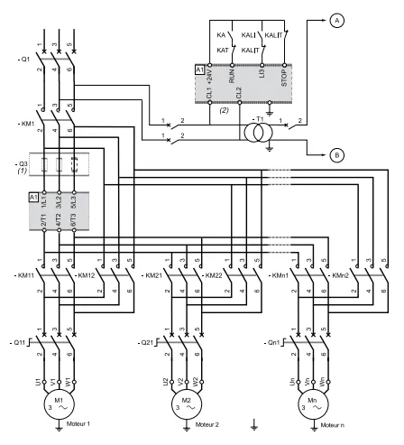
Asynchronous motor starting systems
Introduction
When a motor is switched on, there is a high inrush current from the mains which may, especially if the power line section is inadequate, cause a drop-in voltage likely to affect receptor operation. This drop may be severe enough to be noticeable in lighting equipment. To overcome this, some sector rules prohibit the use of motors with direct on-line starting systems beyond a given power. See pages K34 and K39 of the Distribution BT 1999/2000 catalogue and the tables of voltage drops permitted by standard NF C 15-100.
There are several starting systems which differ according to the motor and load specifications.
The choice is governed by electrical, mechanical and economic factors.
The kind of load driven is also important in the choice of starting system.
Main starting modes
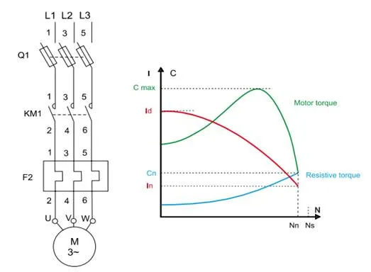
Direct on-line starting
This is the simplest mode, where the stator is directly connected to the mains supply. The motor starts with its own characteristics.
When it is switched on, the motor behaves like a transformer with its secondary, formed by the very low resistance rotor cage, in short circuit. There is a high induced current in the rotor which results in a current peak in the mains supply: Current on starting = 5 to 8 rated Current.
The average starting torque is:
T on starting = 0.5 to 1.5 rated T.
In spite of its advantages (simple equipment, high starting torque, fast start, low cost), direct on-line starting is only suitable when:
- the power of the motor is low compared to that of the mains, which limits interference from inrush current,
- the machine to drive does not need to speed up gradually or has a damping device to limit the shock of starting,
- the starting torque can be high without affecting machine operation or the load that is driven.
Direct on-line starting
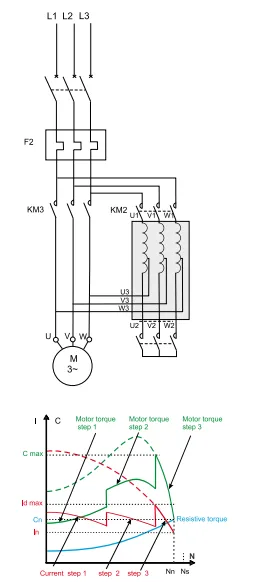
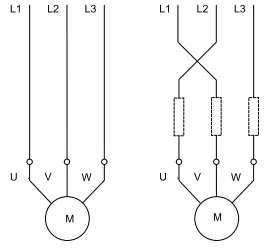
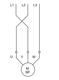
Star-delta starting
This starting system can only be used with a motor where both ends of its three stator windings are fitted to a terminal board. Furthermore, the winding must be done so that the delta connection matches the mains voltage: e.g. a 380V 3-phase supply will need a motor with 380V delta and 660V star coiling.
The principle is to start the motor by connecting the star windings at mains voltage, which divides the motor’s rated star voltage by √ 3 (in the example above, the mains voltage at 400V = 690V / √ 3).
The starting current peak (SC) is divided by 3:
- SC = 1.5 to 2.6 RC (RC rated Current). A
400V / 690V motor star-connected at its rated voltage of 690V absorbs a current ÷3 times less than a delta connection at 380V. With the star connection at 400V, the current is divided by √3 again, so by a total of 3.
As the starting torque (ST) is proportional to the square of the supply voltage, it is also divided by 3:
ST = 0.2 to 0.5 RT (RT Rated Torque)
The motor speed stabilises when the motor and resistive torques balance out, usually at 75-85% of the rated speed. The windings are then delta connected and the motor recovers its own characteristics. The change from star connection to delta connection is controlled by a timer. The delta contactor closes 30 to 50 milliseconds after the star contactor opens, which prevents short-circuiting between phases as the two contactors cannot close simultaneously.
The current through the windings is broken when the star contactor opens and is restored when the delta contactor closes. There is a brief but strong transient current peak during the shift to delta, due to the counterelectromotive force of the motor.
Star-delta starting is suitable for machines with a low resistive torque or which start with no load (e.g. wood-cutting machines). Variants may be required to limit the transient phenomena above a certain power level. One of these is a 1-2 second delay in the shift from star to delta.
Such a delay weakens the counter-electromotive force and hence the transient current peak.
This can only be used if the machine has enough inertia to prevent too much speed reduction during the time delay.
Another system is 3-step starting: star-delta + resistance-delta.
There is still a break, but the resistor in series with the delta-connected windings for about three seconds lowers the transient current. This stops the current from breaking and so prevents the occurrence of transient phenomena.
Use of these variants implies additional equipment, which may result in a significant rise in the cost of the installation.
Star-delta starting
Part winding motor starting
This system, not widely used in Europe, is quite common in the North American market (voltage of 230/460, a ratio of 1:2). This type of motor has a stator winding divided into two parallel windings with six or twelve output terminals. It is equivalent to two “half motors” of equal power.
On starting, a single “half motor” is connected directly at full mains voltage strength, which divides the starting current and the torque approximately by two. The torque is however greater than it would be with a squirrel cage motor of equal power with star-delta starting.
At the end of the starting process, the second winding is connected to the mains. At this point, the current peak is low and brief, because the motor has not been cut off from the mains supply and only has a little slip.
Part winding starting
Resistance stator starting
With this system, the motor starts at reduced voltage because resistors are inserted in series with the windings. When the speed stabilises, the resistors are eliminated, and the motor is connected directly to the mains. This process is usually controlled by a timer.
This starting method does not alter the connection of the motor windings, so the ends of each winding do not need outputs on a terminal board.
The resistance value is calculated according to the maximum current peak on starting or the minimum starting torque required for the resistance torque of the machine to drive. The starting current and torque values are
generally:
- SC = 4.5 RC
- ST = 0.75 RT
During the acceleration stage with the resistors, the voltage applied to the motor terminals is not constant but equals the mains voltage minus the voltage drop in the starting resistance.
The voltage drop is proportional to the current absorbed by the motor. As the current weakens with the acceleration of the motor, the same happens to the voltage drop in the resistance. The voltage applied to the motor terminals is therefore at its lowest on starting and then gradually increases.
As the torque is proportional to the square of the voltage at the motor terminals, it increases faster than in star-delta starting where the voltage remains constant throughout the star connection.
This starting system is therefore suited to machines with a resistive torque that increases with the speed, such as fans and centrifugal pumps.
It has the drawback of a rather high current peak on starting. This could be lowered by increasing the resistance value but that would cause the voltage to drop further at the motor terminals and thus a steep drop in the starting torque.
On the other hand, resistance is eliminated at the end of starting without any break in power supply to the motor, so there are no transient phenomena

Resistance stator starting
Autotransformer starting
The motor is powered at reduced voltage via an autotransformer which is bypassed when the starting process is completed.
The starting process is in three steps:
- in the first place, the autotransformer is star-connected, then the motor is connected to the mains via part of the autotransformer windings. The process is run at a reduced voltage which depends on the transformation ratio. The autotransformer is usually tapped to select this ratio to find the most suitable voltage reduction value,
- the star connection is opened before going onto full voltage. The fraction of coil connected to the mains then acts as an inductance in series with the motor. This operation takes place when the speed balances out at the end of the first step,
- full voltage connection is made after the second step which usually only lasts a fraction of a second. The piece of autotransformer winding in series with the motor is short-circuited and the autotransformer is switched off.
The current and the starting torque vary in the same proportions. They are divided by (mains V/reduced V2).
The values obtained are:
SC = 1.7 to 4 RC
ST = 0.5 to 0.85 RT
The starting process runs with no break in the current in the motor, so transient phenomena due to breaks do not occur.
However, if a number of precautions are not taken, similar transient phenomena can appear on full voltage connection because the value of the inductance in series with the motor is high compared to the motor’s after the star arrangement is open. This leads to a steep drop in voltage which causes a high transient current peak on full voltage connection. To overcome this drawback, the magnetic circuit in the autotransformer has an air gap which helps to lower the inductance value. This value is calculated to prevent any voltage variation at the motor terminals when the star arrangement opens in the second step.
The air gap causes an increase in the magnetising current in the autotransformer. This current increases the inrush current in the mains supply when the autotransformer is energised.
This starting system is usually used in LV for motors powered at over 150kW. It does however make equipment rather expensive because of the high cost of the autotransformer
Autotransformer starting
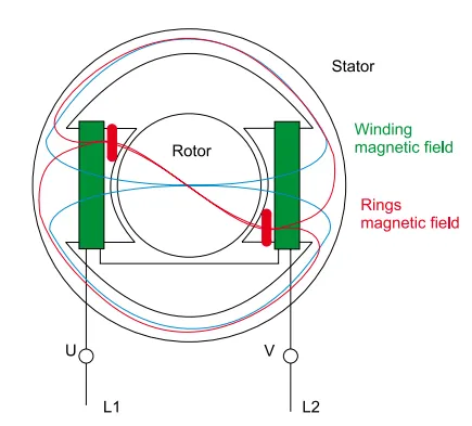
Slip ring motor starting
A slip ring motor cannot be started direct on-line with its rotor windings short-circuited, otherwise it would cause unacceptable current peaks. Resistors must therefore be inserted in the rotor circuit and then gradually short-circuited, while the stator is powered at full mains voltage.
Rotor contactors are dependent on the stator contactor and thus only open after it, once rotor voltage has completely or practically disappeared. These contactors make the current corresponding to the standard start-up peak (1.5 to 2.5 times rotor nominal current) and open the circuit off-load. The diagram shown for connection of the contactors (said to be in W) allows use of contactors of a rating 1.6 times less than current rating.
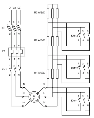
Slip ring motor starting
The resistance inserted in each phase is calculated to ascertain the torque-speed curve with strict accuracy. The result is that it has to be fully inserted on starting and that full speed is reached when it is completely short-circuited.
The current absorbed is more or less proportional to the torque supplied at the most only a little greater than the theoretical value.
For example, for a starting torque equal to 2 RT, the current peak is about 2 RC. This peak is thus much lower and the maximum starting torque much higher than with a squirrel cage motor, where the typical values are about 6 RC for 1.5 RT when directly connected to the mains supply. The slip ring motor, with rotor starting, is the best choice for all cases where current peaks need to be low and for machines which start on full load.
This kind of starting is extremely smooth, because it is easy to adjust the number and shape of the curves representing the successive steps to mechanical and electrical requirements (resistive torque, acceleration value, maximum current peak, etc.).
Soft starter starting/slackening
This is an effective starting system (C Fig.7) for starting and stopping a motor smoothly (see the section on electronic speed controllers for more details). It can be used for: - current limitation, - torque adjustment. Control by current limitation sets a maximum current (3 to 4 x RC) during the starting stage and lowers torque performance. This control is especially suitable for “turbomachines” (centrifugal pumps, fans). Control by torque adjustment optimises torque performance in the starting process and lowers mains inrush current. This is suited to constant torque machines. This type of starter can have many different diagrams: - one-way operation, - two-way operation, - device shunting at the end of the starting process, - starting and slackening several motors in cascade, - etc.
Multiple motor starting with a soft starter
Frequency converter starting
This is an effective starting system to use whenever speed must be controlled and adjusted (see the section on electronic speed control for more details).
Its purposes include:
- starting with high-inertia loads,
- starting with high loads on supplies with low short-circuit capacity,
- optimisation of electricity consumption adapted to the speed of «turbomachines».
This starting system can be used on all types of machines.
It is a solution primarily used to adjust motor speed, started being a secondary purpose.
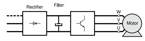
Working diagram of a frequency converter
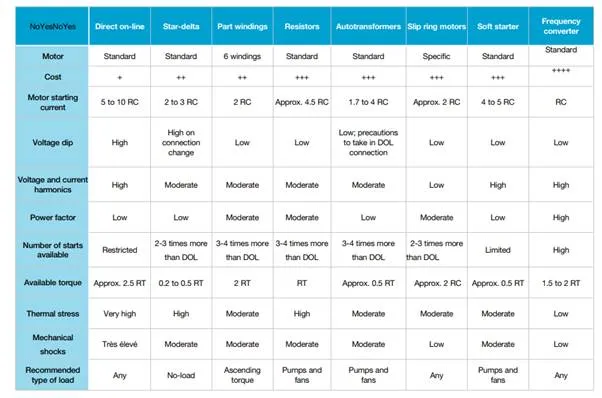
Summary table of 3-phase motor starting systems
This starting system requires the motor to be specifically sized.
Summary table
Single-phase motor starting
A single-phase motor cannot start on its own, so there are different ways to run it.
Auxiliary phase starting
In this type of motor, the stator has two windings geometrically offset by 90°.
When it is switched on, because the coils are made differently, a current C1 crosses the main phase and a weaker current C2, noticeably shifted by p/2, circulates in the auxiliary phase. The fields which are generated are produced by two currents that are phase-shifted in relation to each other, so the resulting rotating field is strong enough to trigger no-load starting of the motor. When the motor has reached about 80% of its speed, the auxiliary phase can be cut off (centrifugal coupling) or kept running. The motor stator thus becomes a two-phase stator, either on starting or all the time.
The connections of a phase can be inverted to reverse the direction of rotation.
As the starting torque is low, it should be raised by increasing the offset between the two fields the coils produce.
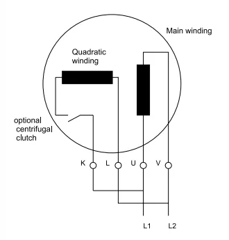
Single-phase motor with auxiliary phase
Auxiliary phase and resistance starting
A resistor in series with the auxiliary phase increases its impedance and the offset between C1 and C2.
Operation at the end of the starting process is the same as with the auxiliary phase on its own.
Auxiliary phase and inductance starting
This works in the same way as above, but the resistor is replaced by an inductance in series with the auxiliary phase to increase the offset between the two currents.
Auxiliary phase and capacitor starting
This is the most widespread device, where a capacitor is set in the auxiliary phase. For a permanent capacitor, the working value is about 8µF for a 200W motor. Starting purposes may require an extra capacitor of 16µF which is eliminated when the starting process is over.
As a capacitor produces a phase shift that is the opposite of an inductance one, during starting and operation, the motor works much like a two-phase one with a rotating field. The torque and power factor are high. The starting torque ST is more or less three times more than the rated torque RT and the maximum torque Tmax reaches 2 RT.
When starting is complete, it is best to maintain the phase-shift between the currents, though the value of the capacity can be reduced because the stator impedance has increased.
The diagram represents a single-phase motor with a permanently-connected capacitor. Other arrangements exist, such as opening the phase-shift circuit by a centrifugal switch when a given speed is reached. A 3-phase motor (230/400V) can be used with a 230V single-phase supply if it is fitted with a starting capacitor and an operating capacitor permanently connected. This operation lessens the working power (derating of about 0.7), the starting torque and the thermal reserve.
Only low-powered 4-pole motors of no more than 4kW are suitable for this system.
Manufacturers provide tables for selecting capacitors with the right values
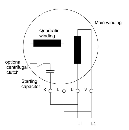
Single-phase motor with starting capacitor
Shaded pole winding starting
This device is used in very low-powered motors (around a hundred watts). The poles have notches with short-circuited conducting rings inserted in them. The induced current this produces distorts the rotating field and triggers the starting process. Efficiency is low but adequate in this power range.
Shaded pole winding motor
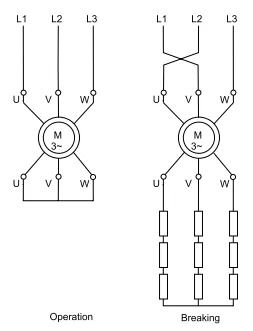
Electrical braking of 3-phase asynchronous motors
Introduction
In a great many systems, motors are stopped simply by natural deceleration. The time this takes depends solely on the inertia and resistive torque of the machine the motor drives. However, the time often needs to be cut down and electrical braking is a simple and efficient solution. Compared to mechanical and hydraulic braking systems, it has the advantage of steadiness and does not require any wear parts.
Countercurrent braking: principle
The motor is isolated from the mains power while it is still running and then reconnected to it the other way around. This is a very efficient braking system with a torque, usually higher than the starting torque, which must be stopped early enough to prevent the motor starting in the opposite direction.
Several automatic devices are used to control stopping as soon as the speed is nearly zero:
- friction stop detectors, centrifugal stop detectors,
- chronometric devices,
- frequency measurement or rotor voltage relays (slip ring motors), etc.
Squirrel cage motor
Before choosing this system, it is crucial to ensure that the motor can withstand countercurrent braking with the duty required of it. Apart from mechanical stress, this process subjects the rotor to high thermal stress, since the energy released in every braking operation (slip energy from the mains and kinetic energy) is dissipated in the cage. Thermal stress in braking is three times more than in speed-gathering.
When braking, the current and torque peaks are noticeably higher than those produced by starting.
To brake smoothly, a resistor is often placed in series with each stator phase when switching to countercurrent. This reduces the torque and current, as in stator starting.
The drawbacks of countercurrent braking in squirrel cage motors are so great that this system is only used for some purposes with low-powered motors.
Principle of countercurrent braking
Slip ring motor
To limit the current and torque peak, before the stator is switched to countercurrent, it is crucial to reinsert the rotor resistors used for starting, and often to add an extra braking section (C Fig.14). With the right rotor resistor, it is easy to adjust the braking torque to the requisite value.
When the current is switched, the rotor voltage is practically twice what it is when the rotor is at a standstill, which sometimes requires specific insulation precautions to be taken.
As with cage motors, a large amount of energy is released in the rotor circuit. It is completely dissipated (minus a few losses) in the resistors.
The motor can be brought to a standstill automatically by one of the above-mentioned devices, or by a voltage or frequency relay in the rotor circuit.
With this system, a driving load can be held at moderate speed. The characteristic is very unstable (wide variations in speed against small variations in torque).
Principle of countercurrent braking in an asynchronous slip ring machine
Braking by injection of DC current
This braking system is used on slip ring and squirrel cage motors. Compared to the countercurrent system, the price of the source of rectified current is offset by fewer resistors. With electronic speed controllers and starters, this braking option does not add to the cost.
The process involves isolating the stator from the mains and sending rectified current to it. The rectified current creates a fixed flux in the air gap of the motor. For the value of this flux to ensure adequate braking, the current must be about 1.3 times greater than the rated current. The surplus of thermal losses caused by this slight overcurrent is usually offset by a pause after braking.
As the value of the current is set by stator winding resistance alone, the voltage at the source of the rectified current is low. The source is usually provided by rectifiers or by speed controllers. These must be able to withstand transient voltage surges produced by the windings that have just been disconnected from the alternating supply (e.g. 380V RMS).
The movement of the rotor is a slip in relation to a field fixed in space (whereas the field spins in the opposite direction in the countercurrent system). The motor behaves like a synchronous generator discharging in the rotor. There are important differences in the characteristics obtained with a rectified current injection compared to a countercurrent system:
less energy is dissipated in the rotor resistors or the cage. It is only equivalent to the mechanical energy given off by masses in movement. The only power taken from the mains is for stator energising,
- if the load is not a driving load, the motor does not start in the opposite direction,
- if the load is a driving load, the system brakes constantly and holds the load at low speed. This is slackening braking rather than braking to a standstill. The characteristic is much more stable than in countercurrent.
With slip ring motors, the speed-torque characteristics depend on the choice of resistors.
With squirrel cage motors, the system makes it easy to adjust the braking torque by acting on the energising direct current. However, the braking torque will be low when the motor runs at high speed.
To prevent superfluous overheating, there must be a device to cut off the current in the stator when braking is over.
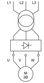
Principle of direct current braking in an asynchronous machine
Electronic braking
Electronic braking is achieved simply with a speed controller fitted with a braking resistor. The asynchronous motor then acts as a generator and the mechanical energy is dissipated in the baking resistor without increasing losses in the motor.
For more information, see the section on electronic speed control in the motor starter units chapter.
Braking by over synchronous operation
This is where a motor’s load drives it above its synchronous speed, making it act like an asynchronous generator and develop a braking torque. Apart from a few losses, the energy is recovered by the mains supply.
With a hoisting motor, this type of operation corresponds to the descent of the load at the rated speed. The braking torque exactly balances out the torque from the load and, instead of slackening the speed, runs the motor at constant speed. On a slip ring motor, all or part of the rotor resistors must be short-circuited to prevent the motor being driven far above its rated speed, which would be mechanically hazardous. This system has the ideal features for restraining a driving load:
- the speed is stable and practically independent of the driving torque,
- the energy is recovered and restored to the mains.
However, it only involves one speed, approximately that of the rated speed.
Over synchronous braking systems are also used on multiple-speed motors to change from fast to slow speed.
Over synchronous braking is easily achieved with an electronic speed controller, which automatically triggers the system when the frequency setting is lowered.
Other braking systems
Single-phase braking can still sometimes be found. This involves powering the motor between two mains phases and linking the unoccupied terminal to one of the other two connected to the mains. The braking torque is limited to 1/3 of the maximum motor torque. This system cannot brake the full load and must be backed by counter current braking. It is a system which causes much imbalance and high losses.
Another system is braking by eddy current slackening. This works on a principle similar to that used in industrial vehicles in addition to mechanical braking (electric speed reducers). The mechanical energy is dissipated in the speed reducer. Braking is controlled simply by an excitation winding. A drawback however is that inertia is greatly increased.
Reversing
3-phase asynchronous motors are put into reverse by the simple expedient of crossing two windings to reverse the rotating field in the motor.
The motor is usually put into reverse when at a standstill. Otherwise, reversing the phases will give counter current braking (see the paragraph on the Slip ring motor). The other braking systems described above can also be used.
Single-phase motor reversing is another possibility if all the windings can be accessed.
Principle of asynchronous motor reversing
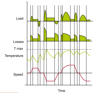
Types of duty
For an electrical motor, number of starting and braking per unit of time have a large incidence on the internal temperature. The IEC standard: Rotating electrical machines - Part 1: Rating and performance (IEC 60034-1:2004) gives the service factors which allow to calculate the heat generated ad size correctly a motor according to the operation. The following information is an overview of these service factors. Additional information will be found in the relevant IEC standard and the manufacturers’ catalogues.
Continuous duty - type D1
Constant-load operation lasting long enough to reach thermal equilibrium
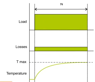
Continuous duty - type D1
Temporary duty – type D2
Constant-load operation for a given period of time, less than required to reach thermal equilibrium, followed by a pause to restore thermal equilibrium between the machine and the surrounding coolant at around 20° C.
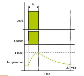
Temporary duty - type D2
Periodic intermittent duty - type D3
Series of identical cycles, each with a period of operation and a pause. The starting current in this type of duty is such that it has no significant effect on heating.
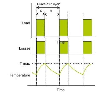
Periodic intermittent duty - type D3
Periodic intermittent duty with starting - type D4
Series of identical cycles, each with a significant starting period, a period of constant-load operation and a pause.
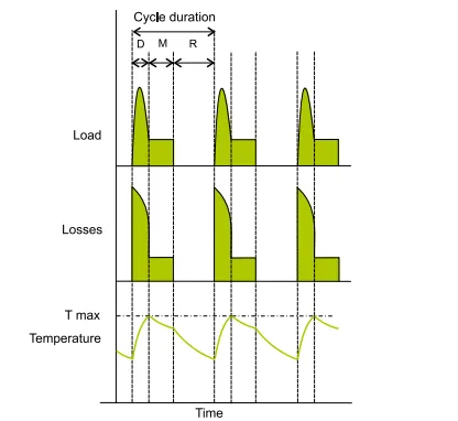
Periodic intermittent duty with starting - type D4
Periodic intermittent duty with electrical braking - type D5
Series of duty cycles, each with a starting period, a period of constant load operation, a period of electrical braking and a pause.
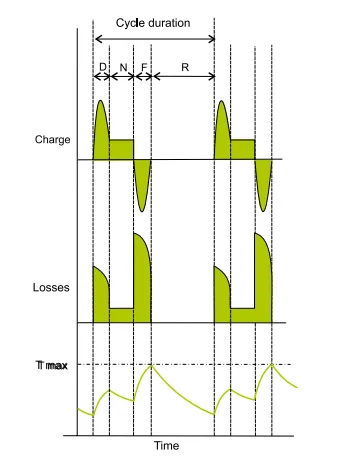
Periodic intermittent duty with electrical braking - type D5
Periodic continuous duty with intermittent load - type D6
Series of identical duty cycles, each with a period of constant-load operation and a period of no-load operation. There is no pause.

Periodic continuous duty with intermittent load - type D6
Periodic continuous duty with electrical braking - type D7
Series of identical duty cycles, each with a starting period, a period of constant-load operation and a period of electrical braking. There is no pause.
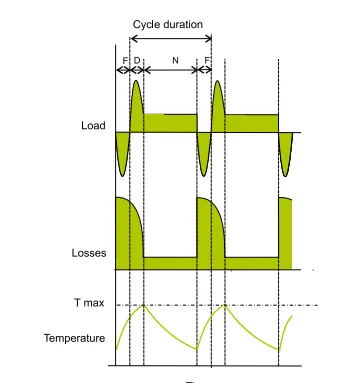
Periodic continuous duty with electrical braking - type D7
Periodic continuous duty with load-speed-linked changes - type D8
Series of identical duty cycles, each with a period of constant-load operation at a preset rotation speed, followed by one or more periods of constant-load operation at other speeds (e.g. by changing the number of poles). There is no pause.
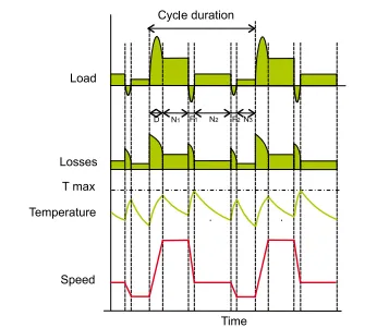
Periodic continuous duty with load-speed linked cange - type D8
Non-periodic load and speed variation duty - type D9
Duty where load and speed usually vary non-periodically within an allowed operating range. This duty often includes overloads which can be much higher than full load.
Non-periodic load and speed variation dutyl - type D9
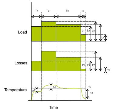
Separate constant-rate duty - type D10
Duty with at most four separate load values (or equivalent load values), each one applied long enough for the machine to reach thermal equilibrium. The minimum load in a load cycle can be zero (no-load operation or pause).
Separate constant-rate duty - type D10